Production device of building heat preservation vacuum insulation panel core material

A technology of vacuum insulation panels and production equipment, which is applied in the directions of transportation and packaging, dissolving, mixing machines, etc., which can solve the problems of non-planar non-planar fields, the inability to ensure uniform slurry composition, and complicated operation steps, so as to avoid Adverse effects, improving dehydration efficiency and quality, and improving the effect of salvage quality

Inactive Publication Date: 2022-02-08
深圳市森木装饰工程有限公司
View PDF0 Cites 1 Cited by
  • Summary
  • Abstract
  • Description
  • Claims
  • Application Information

AI Technical Summary

Problems solved by technology

With the expansion of the practical field of vacuum insulation panels, the simple flat type can no longer meet the requirements of some non-planar fields.
For example, circular or arc-shaped structures have typical aesthetic characteristics and are often used in the construction field. Therefore, the insulation of these arc-shaped parts requires a

Method used


Image

  • Production device of building heat preservation vacuum insulation panel core material
  • Production device of building heat preservation vacuum insulation panel core material
  • Production device of building heat preservation vacuum insulation panel core material

Examples


Embodiment 1

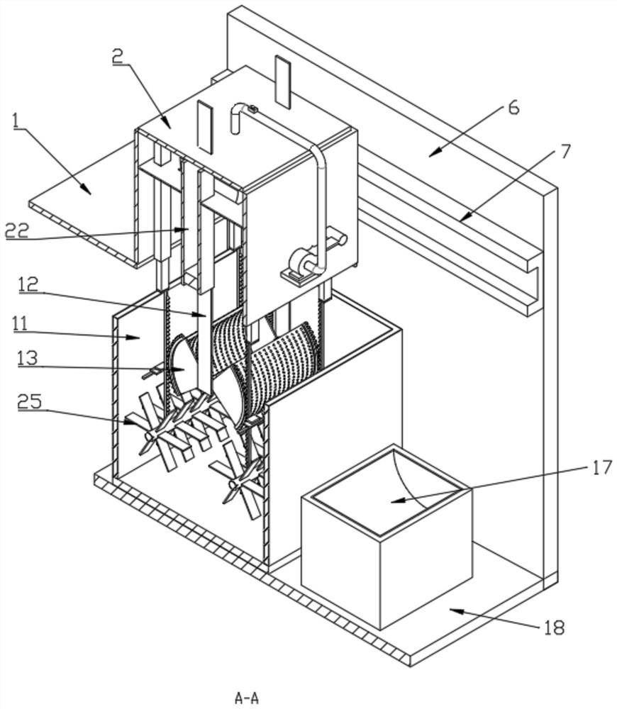
[0042] Embodiment 1, an embodiment for driving two stirring rods 25 to rotate, the inner wall of the slurry tank 11 is fixedly equipped with an engagement mechanism for driving the rotation of the two stirring rods 25, and the engagement mechanism includes The fixed bar 27 on the inner wall, the movable block 29 is slidably installed on the fixed bar 27, the first spring 28 is connected between the movable block 29 and the bottom of the fixed bar 27, the first spring 28 is fixed on the movable block 29, the stirring rod 25 The outer wall is distributed with the second teeth 33 meshed with the second rack 26, the top of the second rack 26 is fixedly connected with the extension block 30, and the side wall of the first rack 16 is fixedly installed with a press for pressing the extension block 30. Block 31.

[0043] Through the agitating mechanism provided, when the vertical bar 12 moves downwards, the first rack 16 can be further moved downward, and when the pressing block 31 co...

Embodiment 2

[0044] Embodiment 2, another embodiment for driving two stirring rods 25 to rotate, further, two motors 32 are fixedly installed on the outer wall of the slurry tank 11, and the two motors 32 are used to drive the two stirring rods 25 Opposite rotation occurs.

[0045] Through the two motors 32 provided, the two motors 32 can be driven to rotate in different directions, and the slurry inside the slurry tank 11 can be agitated by turning to avoid its settlement.

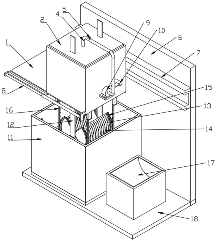
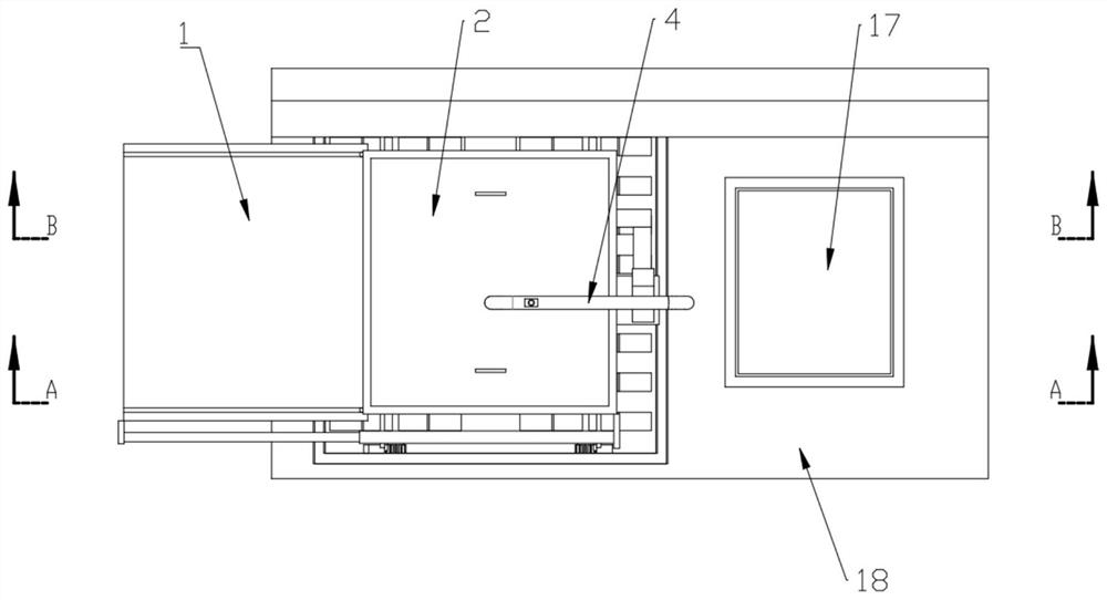
[0046] Further, a receiving box 17 for receiving materials is fixedly installed on the upper surface of the bottom plate 18 .

[0047] When the dehydration box 2 is located directly below the receiving box 17, the electric telescopic rod 8 drives the sealing plate 1 to open again. Similarly, when the vertical bar 12 drives the arc-shaped mold cover 13 to move downward, the first tooth bar 16 and the second tooth bar 16 move downward. Under the meshing drive of one tooth 15, the two arc-shaped mold sets 13 are gradual...


PUM


Abstract

The invention discloses a production device of a building heat preservation vacuum insulation panel core material. The production device comprises a bottom plate and a backup plate fixed to the upper surface of the bottom plate, a slurry tank for containing slurry is fixedly installed on the upper surface of the bottom plate, a stirring mechanism capable of turning over the slurry is arranged in the slurry tank, and a dewatering box capable of horizontally sliding is connected to the side wall of the backup plate above the slurry tank; a material containing mechanism for fishing slurry is arranged on the dewatering box; the material containing mechanism comprises two second electric sliding rails fixed to the inner wall of the dewatering box, and two arc-shaped mold sleeves are rotationally installed on the opposite faces, close to the bottoms, of the two vertical strips through pin shafts. In the process that the arc-shaped mold sleeve is gradually closed, stirred slurry can be fished, uneven components of the fished slurry are effectively avoided, the fishing quality is improved, and the working efficiency is guaranteed.

Description

technical field [0001] The invention relates to the technical field of vacuum heat insulation board core materials, in particular to a production device for building heat insulation vacuum heat insulation board core materials. Background technique [0002] Vacuum insulation panels have excellent thermal insulation properties. Vacuum insulation panels, also known as VIP panels, are one of the vacuum insulation materials. The vacuum insulation panels currently on the market are composed of filling core materials and vacuum protection surfaces. Effectively avoid heat transfer caused by air convection. As far as their shape is concerned, they are all flat type. With the expansion of the practical field of vacuum insulation panels, the simple flat type can no longer meet the requirements of some non-planar fields. For example, circular or arc-shaped structures have typical aesthetic characteristics and are often used in the construction field. Therefore, the insulation of these...

Claims


Application Information

Patent Timeline
IPC IPC(8): B01F31/441
Inventor 韩海清
Owner 深圳市森木装饰工程有限公司
Why Eureka
Try Eureka