
Self-moving type vehicular bridge for striding over belt conveyors

A belt conveyor, self-moving technology, used in pedestrian bridges, bridges, bridge parts, etc., can solve the problems of poor mobility of rigid road bridges, inability to change the installation position, cumbersome anchor bolt fixing, etc. The effect of reducing the space occupied and the trouble of assembling and disassembling the auxiliary bridge body, and improving the work efficiency

Active Publication Date: 2017-05-10
LIAONING TECHNICAL UNIVERSITY +1
View PDF5 Cites 10 Cited by
  • Summary
  • Abstract
  • Description
  • Claims
  • Application Information

AI Technical Summary

Problems solved by technology

However, the rigid driving bridge manually overlapped has poor mobility, and its installation position cannot be changed. If the transportation route is changed, the driving bridge needs to be re-lapped to meet the layout requirements of the transportation route.
In addition, there is also a patent with application number 2015110255016, which provides a movable bridge body used in the field of road construction to provide temporary passage for small vehicles, but the bridge body has no power source, In the process of moving, it needs to be dragged by a tractor vehicle, which is inconvenient to use; the connection between the main and auxiliary bridges is connected by a detachable connection, but in the field of open-pit mining, due to the heavy load of the transport vehicle, the bridge is easy to be damaged. Even lead to the occurrence of accidents; and the support of the bridge body needs to be fixed with bolts, but it is also cumbersome to use anchor bolts at the open-pit mine site

Method used


Image

  • Self-moving type vehicular bridge for striding over belt conveyors
  • Self-moving type vehicular bridge for striding over belt conveyors
  • Self-moving type vehicular bridge for striding over belt conveyors

Examples


Embodiment Construction

[0020] The present invention will be further described in detail below in conjunction with the accompanying drawings and specific embodiments.

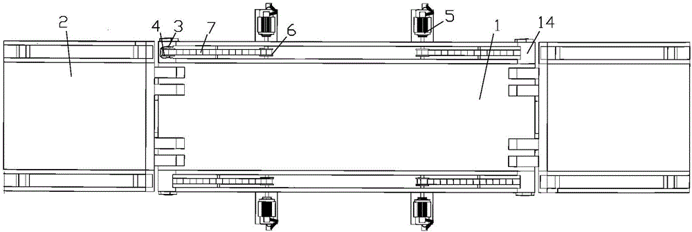
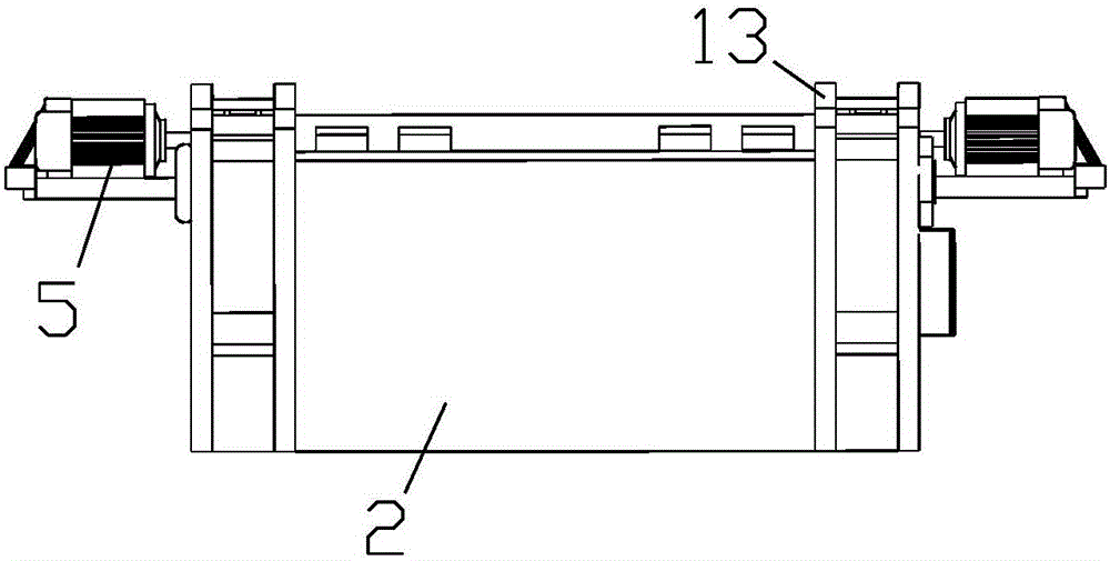
[0021] Such as Figure 1 to Figure 4 As shown, a self-moving driving bridge for crossing belt conveyors belongs to the transportation auxiliary equipment for open-pit mining. The transportation route of the vehicle.

[0022] The self-moving driving bridge used for cross-belt conveyor of the present invention includes a main bridge body 1 and two auxiliary bridge bodies 2, one end of the auxiliary bridge body 2 is fixed with a transmission shaft 3, and both ends of the transmission shaft 3 are provided with first chains. Wheel 4, the two opposite ends of the main bridge body 1 in the length direction are respectively hinged with the two auxiliary bridge bodies 2 through the transmission shaft 3 to form an arc-shaped bridge deck, and the transmission shaft 3 can rotate relative to the main bridge body 1. The upper surface of the main ...


PUM


Abstract

The invention provides a self-moving type vehicular bridge for striding over belt conveyors, and belongs to the technical field of open-cast mining. The vehicular bridge comprises a main bridge body and auxiliary bridge bodies. A transmission shaft is fixed at one end of each auxiliary bridge body, and first chain wheels are arranged at the two ends of each transmission shaft. The two opposite ends in the length direction of the main bridge body are hinged to the auxiliary bridge bodies through the transmission shafts, so that an arc-shaped bridge deck is formed. The two opposite ends in the width direction of the main bridge body are each provided with two speed reduction motors. Second chain wheels are arranged at the output ends of the speed reduction motors. Each second chain wheel is connected with the adjacent first chain wheel through a transmission chain. First lifting hydraulic cylinders are fixed at the two opposite ends in the length direction of the main bridge body separately, and pier supports are arranged at the bottoms of the first lifting hydraulic cylinders. A main lifting hydraulic cylinder is fixed in the center of the lower surface of the main bridge body. The belt conveyors can pass through the spaces between the main lifting hydraulic cylinder and the first lifting hydraulic cylinders. The bottom of the main lifting hydraulic cylinder is rotationally connected to a tracked carrier. The vehicular bridge provided by the invention is convenient to move, and the erecting position of the vehicular bridge can be moved and changed according to setting of different transportation lines.

Description

technical field [0001] The invention belongs to the technical field of open-pit mining, in particular to a self-moving driving bridge used for crossing belt conveyors. Background technique [0002] The mining industry is the foundation of the national economy, and it undertakes the task of providing coal and various minerals and raw materials. With the development of my country's economy, the technical transformation of the original mining equipment is also urgent, using high-quality, high-efficiency, high-economic-benefit mining machinery and equipment to equip mines, so as to improve the development level of my country's mining industry technology. Among them, the production efficiency of open-pit mining is 3-7 times higher than that of mine mining, and it has the advantages of production safety and good working conditions, making it have broad development prospects and attracting attention from all over the world. In the past 40 years, open-pit coal mining has been great...

Claims


Application Information

Patent Timeline
IPC IPC(8): E01D15/10E01D19/02E01D19/04E01D19/12E01D19/10
CPCE01D15/10E01D19/02E01D19/04E01D19/10E01D19/12
Inventor 曹博刘光伟李浩然韩新平刘天一高志龙张金龙
Owner LIAONING TECHNICAL UNIVERSITY
Learn More