
A steel pipe pile with hinged enlarged head

A technology of steel pipe pile and enlarged head, applied in sheet pile wall, construction, infrastructure engineering and other directions, can solve the problems of easy infiltration of soil particles, increase construction cost, limited uplift and compression bearing capacity, etc., and achieve the expansion effect. range, increasing shear strength, increasing the effect of contact area

Active Publication Date: 2018-11-27
NANJING TECH UNIV
View PDF3 Cites 0 Cited by
  • Summary
  • Abstract
  • Description
  • Claims
  • Application Information

AI Technical Summary

Problems solved by technology

However, the traditional steel pipe piles have single functions and limited pullout and compression bearing capacity. The following points are particularly obvious:
[0003] 1. In some soft soil layers with high groundwater level, the pile body has insufficient anti-lifting and anti-floating performance under the buoyancy of groundwater
Based on this, some scholars have developed a new type of umbrella-shaped anchor to improve the pull-out performance of piles. However, due to the small contact area between the umbrella-shaped rib skeleton and the soil, the range of covering the soil is very limited, and the improvement of the pull-out performance is not obvious in practical applications.
[0004] 2. The hinged structure of the tip of the existing umbrella-shaped anchor has a large friction during the sinking process, which is easy to penetrate into the soil particles, making the sinking angle of the tendon skeleton difficult to meet the expectation, and the improvement of the pullout resistance is limited
[0005] 3. When the bearing capacity of traditional steel pipe piles does not meet the requirements, the problem is usually solved by increasing the pile diameter and pile length, which increases the construction cost

Method used


Image

  • A steel pipe pile with hinged enlarged head
  • A steel pipe pile with hinged enlarged head
  • A steel pipe pile with hinged enlarged head

Examples


Embodiment Construction

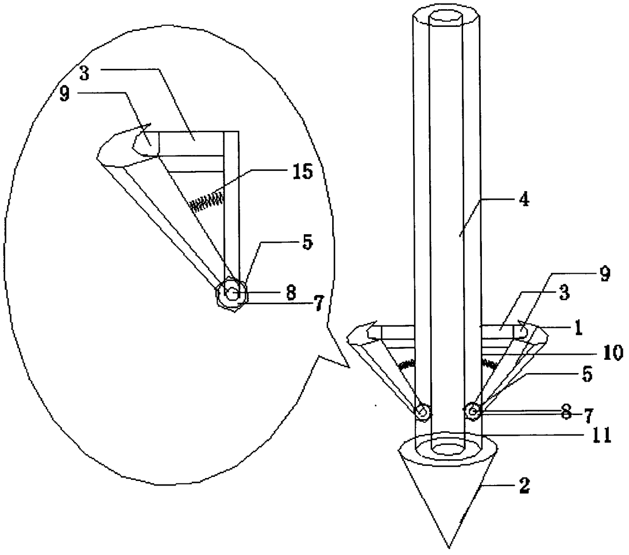
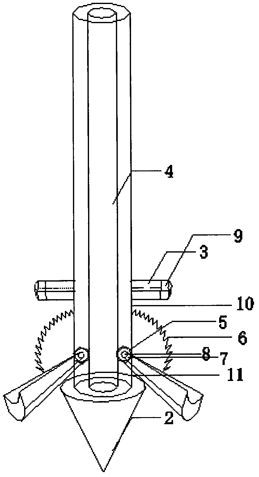
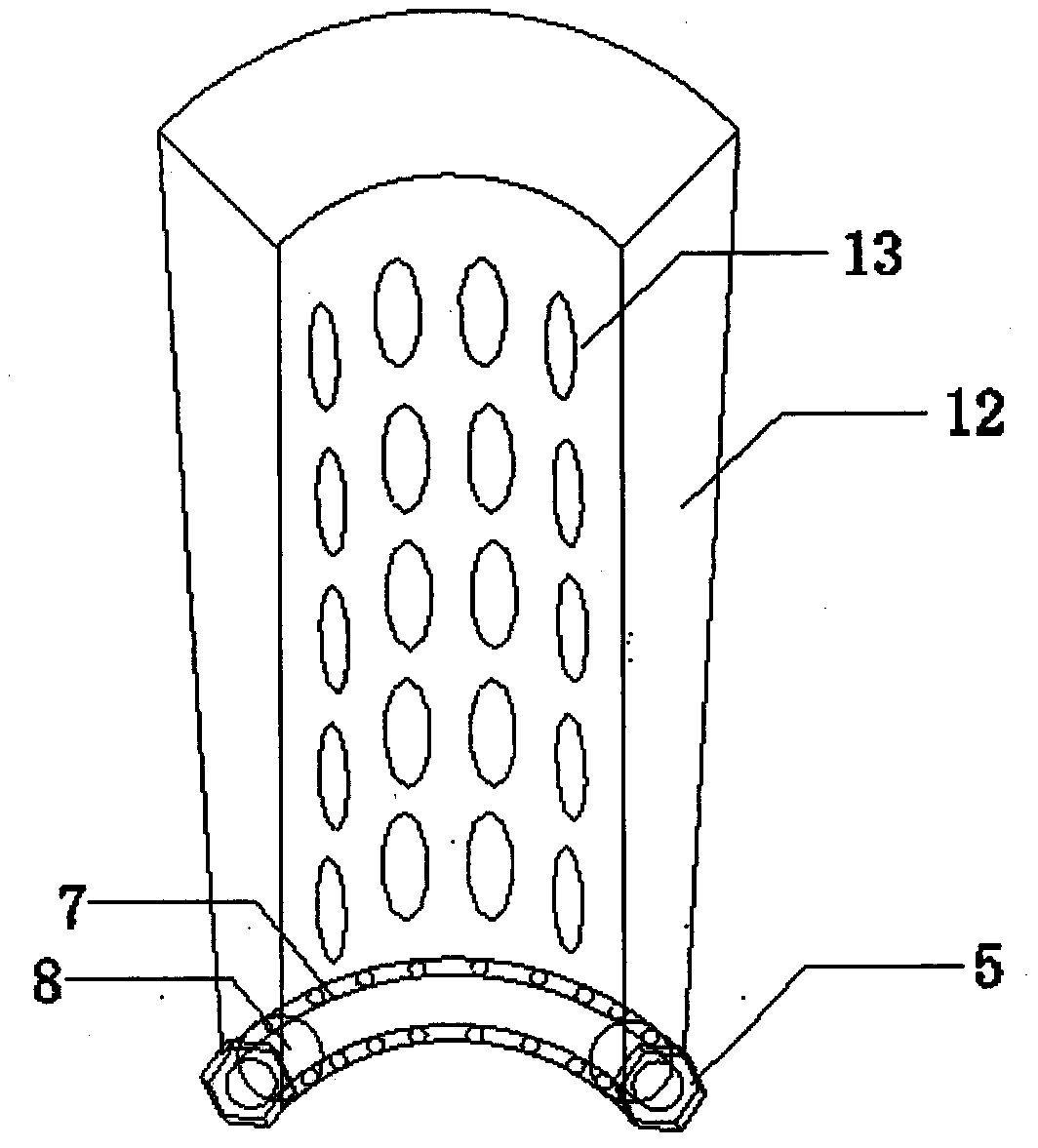
[0023] see Figure 1-4 As shown, a steel pipe pile with a hinged enlarged head includes a variable thickness hollow steel sheet 1, a ball bearing 7 is welded at the end of the steel pipe pile, a rotating shaft 8 is nested in the ball bearing 7, and the rotating shaft 8 is connected to the variable thickness hollow steel sheet. The steel sheet 1 is fixed by two symmetrical bolts 5 . Spray ports 10 and 11 are respectively arranged on the upper and lower sides of the rotating shaft, and a magnet fixing device 3 is welded above the position of the spraying port 10 on the upper part of the rotating shaft, and the magnet block 9 is fixed on the magnet fixing device, and a spring is connected to the rotating shaft and the pile body 6. The ball bearing 7 is 1 / 4 arc-shaped, symmetrically welded to the end of the pile body, and bolt holes are symmetrically arranged at both ends.

[0024] Bolt holes are symmetrically arranged at the ends of the variable-thickness hollow steel sheet 1 . ...


PUM


Abstract

The invention discloses a hinge enlarging head steel pipe pile and belongs to the field of geotechnical engineering. The hinge enlarging head steel pipe pile comprises a variable-thickness hollow steel sheet, a conical pile tip, a magnet, a magnet fixing device, a pile body, a bolt, a spring, a ball bearing, a rotary shaft, and guniting holes in the upper position and the lower position of the rotary shaft. Compared with the prior art, firstly, high-speed cement paste is sprayed from the guniting hole in the lower portion of the rotary shaft, and negative pressure is formed at the bottom of the steel sheet. High-pressure guniting is carried out on the guniting hole in the upper portion of the rotary shaft, and the variable-thickness hollow steel sheet is pushed away from the magnet through guniting pressure, and the steel sheet rotates downwards around the rotary shaft under the effects of the lower negative pressure, the upper guniting pressure, the self gravity and the spring elasticity to fall to the conical pile tip to be almost in a horizontal state. An effective enlarging jet-grouted solid is formed around the steel sheet by soil mass and cement grout after guniting is completed. The anti-pulling and anti-pressing performance of the steel pipe pile can be remarkably improved.

Description

technical field [0001] The invention relates to the field of geotechnical engineering, in particular to the field of steel pipe piles, in particular to a steel pipe pile with a hinged enlarged head. Background technique [0002] Steel pipe piles have the characteristics of flexible pile location selection, simple layout, economical and practical, and low site requirements. In recent years, they have been widely used in the fields of offshore platforms, foundation reinforcement, foundation pit support, and landslide control. According to reliable data, my country's steel output reached 1.1 billion tons in 2015, but the utilization rate was less than 67%. The overcapacity of steel has greatly reduced the cost of steel pipe piles, which has greatly promoted it in the field of geotechnical engineering. However, the traditional steel pipe piles have single functions and limited pullout and compression bearing capacity. The following points are particularly obvious: [0003] 1. I...

Claims


Application Information

Patent Timeline
Patent Type & Authority Patents(China)
IPC IPC(8): E02D5/28
CPCE02D5/285
Inventor 刘加才史文韬王旭东
Owner NANJING TECH UNIV
Learn More