
Shied cutter head abrasion repairing construction method in tunnel

A wear repair and shield cutter head technology, applied in tunnels, earth-moving drilling, mining equipment, etc., can solve the problems of heavy cutter seat, wear of cutter head outer edge, inconvenient replacement, etc., to shorten the construction period and increase stability. The effect of stability and easy replacement

Active Publication Date: 2017-05-10
中铁二十局集团第五工程有限公司
View PDF4 Cites 7 Cited by
  • Summary
  • Abstract
  • Description
  • Claims
  • Application Information

AI Technical Summary

Problems solved by technology

For the stratum with a high coverage rate of surface houses and mostly old earth-brick houses without foundation, in order to control the settlement of the ground houses in the composite stratum, a full warehouse high-pressure excavation mode is adopted, which will cause the shield machine to be under large pressure for a long time. Under the harsh working conditions of thrust, large torque, and partial load, the outer edge of the cutter head is severely worn, and the cutter head of the shield machine needs to be repaired in time. The existing shield machine cutter head repairs mostly use the method of digging a well on the ground to repair the shield machine. Repairing the machine cutter head, the construction cost is high, the process is complicated, and the construction period is seriously affected; in addition, the existing replacement tool holders are mostly replaced by conventional replacement, the space in the tunnel is small, the tool holders are heavy, and the replacement is inconvenient, which brings inconvenience to the construction. Unnecessary troubles were caused, which seriously affected the construction period

Method used


Image

  • Shied cutter head abrasion repairing construction method in tunnel
  • Shied cutter head abrasion repairing construction method in tunnel
  • Shied cutter head abrasion repairing construction method in tunnel

Examples


Embodiment Construction

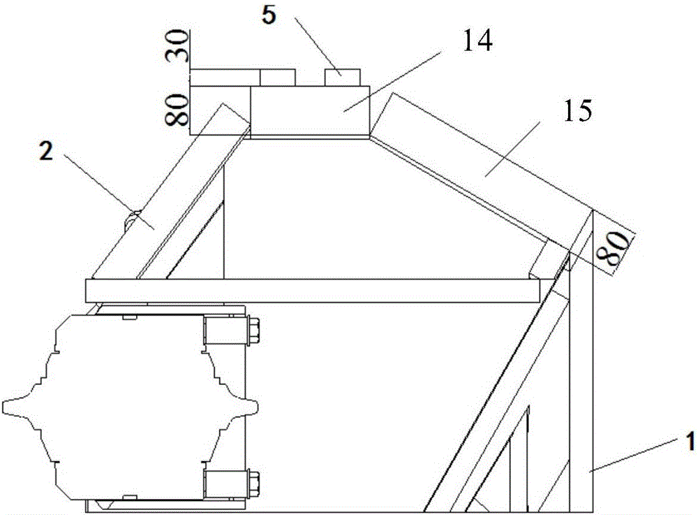
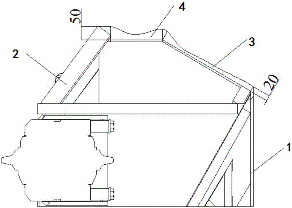
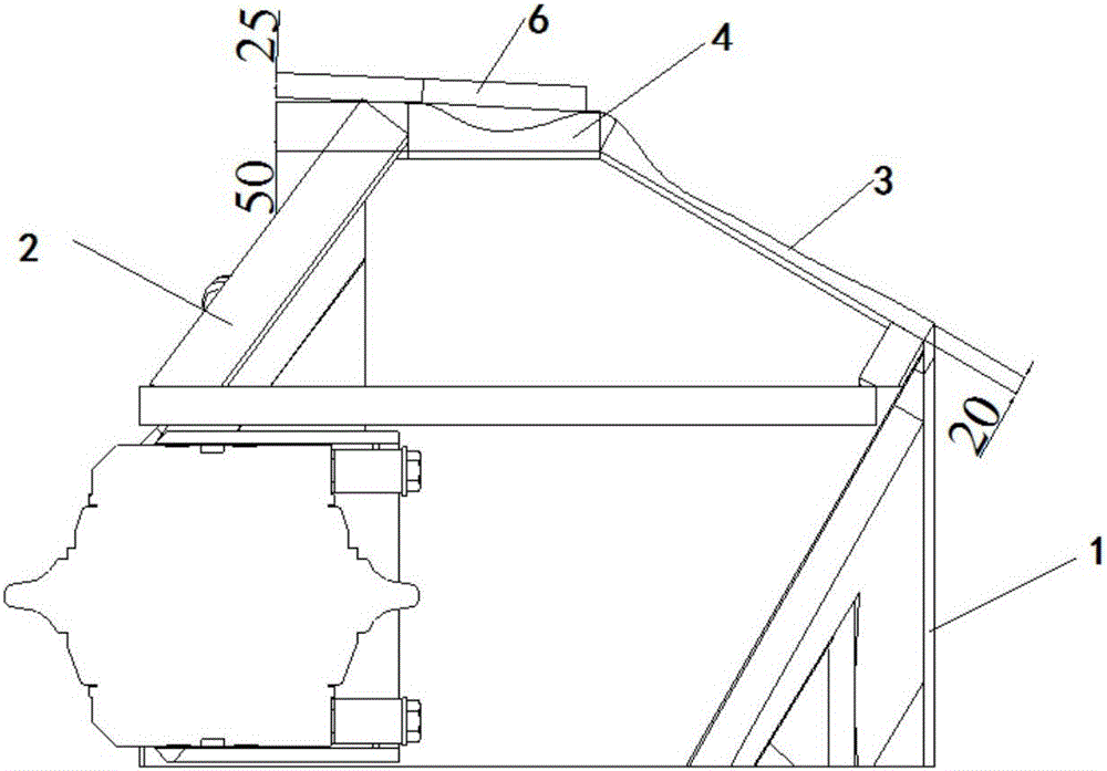
[0048] Such as Figure 1 to Figure 13 As shown, the wear repair construction method in the shield cutterhead tunnel of the present invention comprises the following steps:

[0049] Step 1. Excavate the cutter head in the tunnel to repair the working space: the shield machine is excavated until the full-section hard rock stops running, and the working space is repaired by manually digging the cutter head by taking advantage of the stability of the tunnel face at the position of the full-section hard rock;

[0050] The working space for repairing the cutterhead is a three-dimensional space with a depth of 1m in the direction of the twelve o'clock of the cutterhead and 0.5m from the top of the shield shell 1;

[0051] In actual construction, the shield machine enters the full-section hard rock, and utilizes the stability of the face of the full-section hard rock to repair the wear of the cutter head in the tunnel, avoiding the need to open a well on the ground and repair the wear...


PUM


Abstract

The invention discloses a shied cutter head abrasion repairing construction method in a tunnel. The method comprises the steps that first, cutter head repairing working space in the tunnel is digged; second, cutter head outer edge abrasion is repaired in the tunnel, specifically, 201, outer edge big ring abrasion is repaired, 202, notch ring abrasion is repaired, and 203, inclined-plane folded plate abrasion is repaired; and third, cutter head panel abrasion is repaired in the tunnel, specifically, 301, big scraper tool apron abrasion is repaired, 302, outer ring small scraper tool apron abrasion is repaired, and 303, abrasion of a hob knife box weld seam is repaired. The design is novel, cutter head abrasion repairing in the tunnel is conducted utilizing steadiness of a tunnel face in a whole fracture surface hard rock position, ground well opening is avoided, cost is saved, meanwhile, a scraper tool apron which is prefabricated and designed with a positioning through hole is adopted to cover welding construction, the situation that location is difficult when an original heavy scraper tool apron is mounted is avoided, so that cost is saved, the construction period is shortened, and replacing of the scraper tool apron in small space is convenient and feasible.

Description

technical field [0001] The invention belongs to the technical field of repairing shield cutterheads, and in particular relates to a construction method for repairing wear and tear in tunnels of shield cutterheads. Background technique [0002] The shield machine is mostly used for underground tunnel construction. During the construction process, the tunnel geology is complex and most of them are composite strata, that is, full-section soft rock, upper soft rock and lower hard rock, and full-section hard rock alternately appear. It is used as a key component of the shield machine during the excavation process. One of the cutterheads plays the role of excavating the ground, supporting the tunnel face, and mixing the slag. Its working conditions are extremely harsh and the stress is complicated. It is the main part of the inspection and maintenance of the shield machine. The quality of the cutterhead will directly affect Whether the shield construction can be carried out smooth...

Claims


Application Information

Patent Timeline
IPC IPC(8): E21D9/08
CPCE21D9/08
Inventor 吕岩张云飞加武荣刘晓勇乔文件张涛涛谭高福黄海波师永
Owner 中铁二十局集团第五工程有限公司
Learn More