

Idling-stop system, method and device for crane
A crane and idling technology, applied in mechanical equipment, engine control, machine/engine, etc., can solve the problems of reducing engine service life, fuel consumption, engine idling, etc., and achieve the effect of ensuring service life and avoiding fuel consumption and wear
- Summary
- Abstract
- Description
- Claims
- Application Information
AI Technical Summary
Problems solved by technology
Method used
Image

Examples
Embodiment 1
[0049] This embodiment provides a crane idling flameout system, the crane idling flameout system uses a controller to control the engine of the crane in the idling state to perform flameout operation.
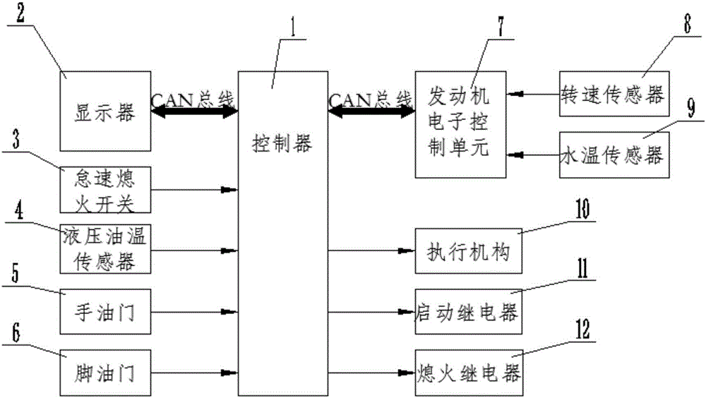
[0050] see figure 1 The crane idling flameout system is shown in the structural diagram, the crane idling flameout system includes: controller 1, idle flameout mode switching switch 3, hydraulic oil temperature sensor 4, throttle module, actuator 10, start relay 11, flameout relay 12, Engine electronic control unit 7, rotational speed sensor 8 and water temperature sensor 9;
[0051] The above-mentioned controller 1 is respectively connected with the above-mentioned idle stop mode switching switch 3, the above-mentioned hydraulic oil temperature sensor 4, the above-mentioned throttle module, the above-mentioned actuator 10, the above-mentioned starting relay 11, the above-mentioned flame-out relay 12, and the above-mentioned engine electronic control unit 7; The electronic con...
Embodiment 2
[0076] This embodiment provides a crane idling flameout method, which is used in the crane idling flameout system of the above embodiment.
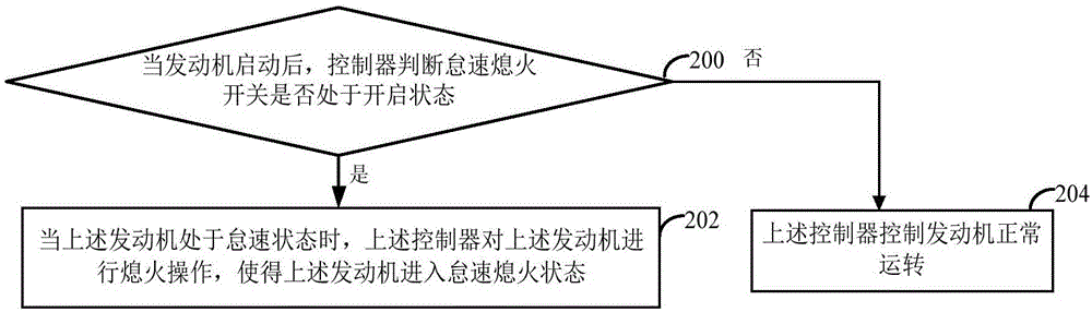
[0077] see figure 2 , a crane idling flameout method, comprising the following specific steps:
[0078] Step 200, when the engine is started, the controller judges whether the idle stop switch is on, if yes, execute step 202, if not, execute step 204.
[0079] Specifically, the above step 200 includes the following steps (1) to (3):
[0080] (1) After the engine is started, the controller sends a switch state acquisition instruction to the idle stop switch, so that the idle stop switch feeds back the current switch state information of the idle stop switch to the controller, and the previous switch state information records the switch state identification;
[0081] (2) Obtain the switch state information fed back by the above-mentioned idle flameout switch;
[0082] (3) Judging whether the switch state identification recorded in the s...
Embodiment 3
[0131] see Figure 4 , this embodiment proposes a crane idling flameout device, which is used in the controller described in the above embodiment; the crane idling flameout device includes:
[0132] Judging module 400, used for judging whether the idle stop switch is on after the engine is started;
[0133] The idle stop module 402 is configured to perform a stop operation on the engine when the engine is in an idle state, so that the engine enters an idle stop state if the judgment result obtained by the judgment module is yes.
[0134] In summary, the crane idling flameout device provided in this embodiment, in the "idling automatic flameout" mode, controls the engine of the crane in the idling state through the controller to perform flameout operation, which can only be manually operated by the crane driver in the prior art Compared with engine flameout, the engine can be turned off in time without manual operation, avoiding fuel consumption and wear caused by long-term id...
PUM
 Abstract
Description
Claims
Application Information