
Accumulator fatigue test device and test method

A fatigue test and accumulator technology, applied in the direction of fluid pressure actuation device, fluid pressure actuation system test, mechanical equipment, etc., can solve the problems of long pressure relief time, waste, affecting the efficiency of fatigue test, etc., to shorten the test cycle, increase the pressure relief speed, and improve the efficiency of the pressure fatigue test

Active Publication Date: 2018-06-26
HEFEI GENERAL MACHINERY RES INST
View PDF5 Cites 0 Cited by
  • Summary
  • Abstract
  • Description
  • Claims
  • Application Information

AI Technical Summary

Problems solved by technology

[0003] In recent years, a variety of fatigue test systems have emerged in China. However, the current test devices are often designed for a certain range of pressure values ​​and specific product volumes, and the nominal volume levels of accumulators are divided into 21 levels from 0.4L to 250L. , the design pressure level is divided into 9 levels from 6.3MPa to 63MPa, and the product technical parameters span a large range
At present, there is no fatigue test device that can meet the accumulator test requirements of all nominal volumes and design pressure levels, and if multiple sets of test devices are used to adapt to the fatigue test of accumulators with similar nominal volumes and design pressure levels, it will cause serious damage. big waste
In addition, the existing test system is to relieve pressure through the pressure difference between the test product and the fuel tank, but as the pressure difference decreases, the pressure relief speed will also decrease, and the long pressure relief time also greatly affects the entire fatigue test. efficiency

Method used


Image

  • Accumulator fatigue test device and test method

Examples


Embodiment Construction

[0026] Below by specific embodiment, the present invention will be further described in conjunction with accompanying drawing:

[0027] In the present invention, high pressure refers to the test pressure ≤ 45 MPa, and ultra-high pressure refers to the fatigue test pressure range of the accumulator of 45-70 MPa.

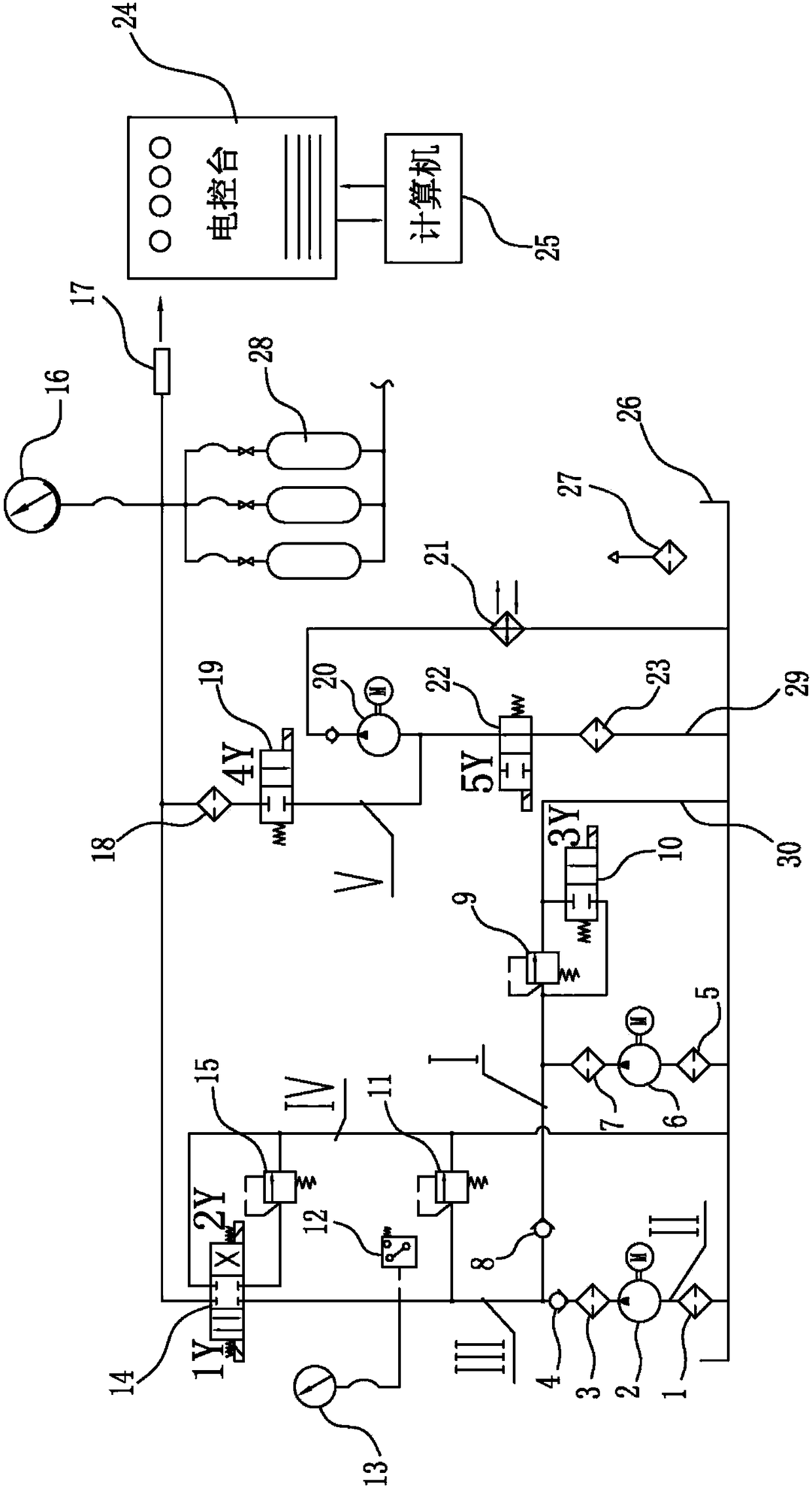
[0028] Such as figure 1 As shown, the accumulator fatigue test device is composed of a hydraulic loading system, a pressure relief system and an automatic control system; wherein, the hydraulic loading system uses a high-pressure oil pump 6 and an ultra-high pressure oil pump 2 as power sources, and consists of a fuel tank 26, a high-pressure oil supply pipe Road I, the low-pressure filter 5, the high-pressure filter 7, and the first one-way valve 8 arranged in series in the high-pressure oil supply line I in sequence, and the first overflow for protecting the system pressure is set on the high-pressure oil supply line I Valve 9 and second cut-off valve 10, ultra-hig...


PUM


Abstract

The invention relates to the technical field of energy accumulator fatigue tests, in particular to an energy accumulator fatigue test device and a test method. The device comprises a loading system and a pressure relieving system; the loading system includes at least two branched oil supply pipelines and a main oil supply pipeline; one ends of all the branched oil supply pipelines are communicated with an oil tank, and the other ends are connected with each other in parallel and communicated with one end of the main oil supply pipeline; the other end of the main oil supply pipeline is communicated with an energy accumulator; two branched oil supply pipelines are respectively provided with high-flow high-pressure oil pumps and low-flow ultrahigh-pressure oil pumps; the pressure relieving system is provided with an oil extracting pump and an oil extracting pipeline; the unloading time of the energy accumulator can be shortened; and the high-volume energy accumulator fatigue test efficiency is further improved. Through pressurizing an energy accumulator shell combination through a high-pressure oil pump motor set and an ultrahigh-pressure oil pump motor set, high-efficiency pressure fatigue tests of all nominal volume grade and design pressure grade energy accumulators in 0-70 MPa are realized.

Description

technical field [0001] The present invention relates to the technical field of accumulator fatigue test, more specifically, it is a fatigue test complete set and test method that can match the loading and unloading modes in the range of 0-70 MPa according to the peak pressure of the fatigue test of the accumulator shell to realize high-efficiency tests . Background technique [0002] As an energy storage device, the accumulator is widely used in hydraulic and pneumatic systems. When the accumulator is working, its shell is subject to frequent pressurization and decompression, which is prone to pressure fatigue failure of the accumulator. Therefore, it is of great significance to study the pressure fatigue strength of the accumulator shell for the safe use of the accumulator. [0003] In recent years, a variety of fatigue test systems have emerged in China. However, the current test devices are often designed for a certain range of pressure values ​​and specific product volu...

Claims


Application Information

Patent Timeline
Patent Type & Authority Patents(China)
IPC IPC(8): F15B19/00
CPCF15B19/007
Inventor 徐鹏郭飞吴苏炜张志伟戴远敬程羊
Owner HEFEI GENERAL MACHINERY RES INST
Learn More