Novel shaft sealing device

A shaft seal, a new type of technology, applied in the direction of engine seals, instruments, program control in sequence/logic controllers, etc., can solve the problems of large power consumption, high noise, and few control functions, and achieve smooth operation. Effect

Inactive Publication Date: 2017-05-10
CHENGDU ZHIRENSHANYONG INFORMATION TECH CO LTD
View PDF0 Cites 0 Cited by
  • Summary
  • Abstract
  • Description
  • Claims
  • Application Information

AI Technical Summary

Problems solved by technology

[0004] The purpose of the present invention is to provide a new type of shaft sealing device to solve the problems of few control functions, high noise and large power consumption in the above-mentioned background technology

Method used


Image

  • Novel shaft sealing device

Examples


Embodiment Construction

[0012] The following will clearly and completely describe the technical solutions in the embodiments of the present invention with reference to the accompanying drawings in the embodiments of the present invention. Obviously, the described embodiments are only some, not all, embodiments of the present invention. Based on the embodiments of the present invention, all other embodiments obtained by persons of ordinary skill in the art without making creative efforts belong to the protection scope of the present invention.

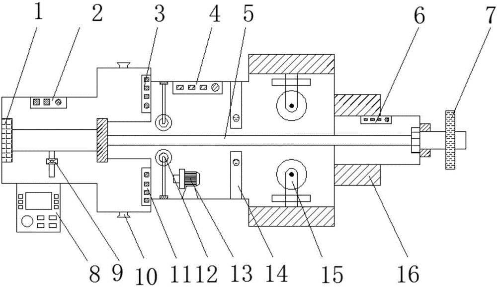
[0013] 2. See figure 1 , an embodiment provided by the present invention: a new type of shaft sealing device, including a seat 1, a shock absorber 3, an alarm device 6, a controller 8, an air port 10 and a guide sleeve 14, and one side of the seat 1 is provided with The muffler 2 is provided with a throttle valve 9 above the controller 8, the energy conversion device 4 is provided on one side of the shock absorber 3, the cylinder 5 is provided below the energy...


PUM


Abstract

The invention discloses a novel shaft sealing device which comprises a pedestal, a shock absorber, an alarm device, a controller, a gas hole and a guide sleeve, wherein a silencer is arranged at one side of the pedestal; a throttle valve is arranged above the controller; an energy conversion device is arranged at one side of the shock absorber; a cylinder sleeve is arranged below the energy conversion device; a fixed base is arranged at one side of the alarm device; a supporting base is arranged below the alarm device; and a sensor is arranged at one side of the gas hole. According to the novel shaft sealing device disclosed by the invention, the silencer and the shock absorber are arranged inside the device, so that the device works and operates more stably; the energy conversion device is arranged at one side of the shock absorber, so that kinetic energy generated by motion of the device is stored in the energy conversion device; in case of insufficient power supply, the energy conversion device is started, so that the sealing device continuously operates; and the alarm device is arranged above the supporting base, so that connection with a power supply is automatically interrupted when the device has faults during an operation period.

Description

technical field [0001] The invention relates to the technical field of sealing devices, in particular to a novel shaft sealing device. Background technique [0002] In the past, we only paid attention to the elimination of visible fluid leakage, but did not pay attention to the control of invisible volatiles, which would cause environmental pollution and be dangerous to devices and people. Foreign countries such as the Sealing Technology Committee of the American Society of Tribology and the Society of Lubrication Engineers have formulated SP-30, SP-32 and SP-33 guidelines for controlling volatile emissions of rotating machinery, compressors and screw systems with mechanical seals. SP-30 is implemented in three phases. It clearly stipulates the definition of blocking fluid and buffer fluid, and clarifies the wrong and confusing concepts. A blocking fluid is a fluid that is introduced between the double seals to completely block leakage of the process fluid to the surroundi...

Claims


Application Information

Patent Timeline
IPC IPC(8): F16J15/00G05B19/04G08B21/18
CPCF16J15/00G05B19/04G08B21/18
Inventor 张凯胜刘华吴小莉
Owner CHENGDU ZHIRENSHANYONG INFORMATION TECH CO LTD
Why Eureka
Try Eureka