The electromagnetic valve
A solenoid valve and valve cavity technology, applied in the field of solenoid valves, can solve the problems of increased necessary force, deterioration of flow characteristics of solenoid valves, and larger overall size, etc.
- Summary
- Abstract
- Description
- Claims
- Application Information
AI Technical Summary
Problems solved by technology
Method used
Image

Examples
no. 1 example
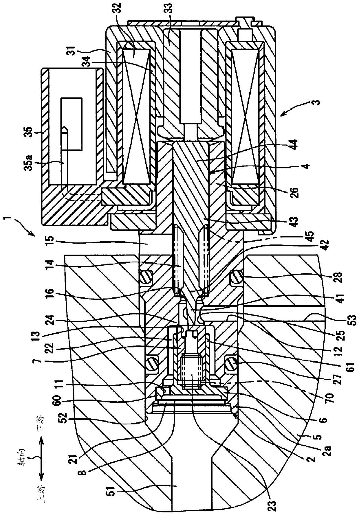
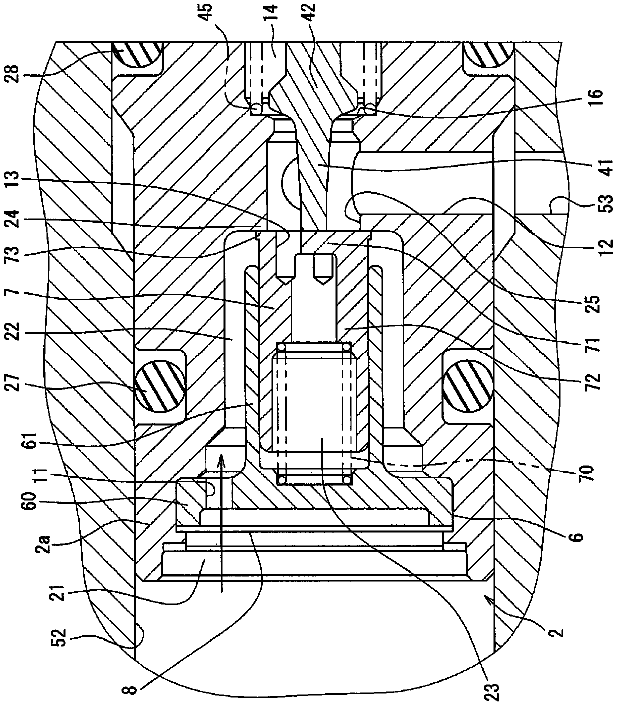
[0015] will refer to Figure 1 to Figure 3 The solenoid valve 1 according to the first embodiment is explained. figure 1 Shown is an overall conventional structure of a solenoid valve 1 installed, for example, in an automatic transmission system of an automobile. Solenoid valve 1 can switch the oil passage to control the shift gearbox. The solenoid valve 1 includes a flow passage control portion housed in a housing 2 and an electromagnetic solenoid portion 3 integrally connected to the flow passage control portion.
[0016] The flow passage control part includes a tubular housing 2 and extends in the axial direction of an attachment hole 52 . The end tubular portion 2a at one end of the housing 2 is fitted and fixed to a mounting hole 52 forming a cylindrical passage in the passage forming member 5 within the automatic transmission or adjacent to the automatic transmission. The passage forming member 5 forms an upstream passage 51 which is an oil inflow passage through whic...
no. 2 example
[0044] will refer to Figure 4A second embodiment of the present invention will be described. In the second embodiment, components assigned with the same reference numerals in the drawings related to the first embodiment and components not described in detail are similar to those in the first embodiment and function in the same manner as the first embodiment. functions and effects. In the second embodiment, only components different from those of the first embodiment are described.
[0045] Such as Figure 4 As shown, the valve element 107 of the second embodiment includes a downstream end portion 173 comprising a pressure receiving portion in the downstream end of the valve element 107 in contact with the valve seat 24 . The pressure receiving portion has a shape with a diameter size gradually decreasing in a downstream direction of the flow of the working fluid. The diameter dimension R4 of the pressure receiving portion portion in contact with the valve seat 24 is small...
no. 3 example
[0047] will refer to Figure 5 A third embodiment of the contents of the present invention will be described. In the third embodiment, components assigned with the same reference numerals in the drawings related to the first embodiment and components not described in detail are similar to the components in the first embodiment and perform the same function as the first embodiment. functions and effects. In the third embodiment, only components different from those of the first embodiment are described.
[0048] Such as Figure 5 As shown, the valve element 207 of the third embodiment includes a downstream end portion 273 projecting radially outwardly from the outer surface of the tubular wall portion 72 . The diameter 273 of the downstream end portion 273 is larger than the diameter of the portion of the tubular wall portion 72 located on the upstream side of the downstream end portion 273 . In other words, the diameter dimension R6 of the downstream end portion 273 is lar...
PUM
 Abstract
Description
Claims
Application Information
 - R&D
- Intellectual Property
- Life Sciences
- Materials
- Tech Scout
- Unparalleled Data Quality
- Higher Quality Content
- 60% Fewer Hallucinations
Browse by: Latest US Patents, China's latest patents, Technical Efficacy Thesaurus, Application Domain, Technology Topic, Popular Technical Reports.
© 2025 PatSnap. All rights reserved.Legal|Privacy policy|Modern Slavery Act Transparency Statement|Sitemap|About US| Contact US: help@patsnap.com