Smoke guiding integrated stove

A technology of integrated stove and stove body, applied in the field of integrated stove, can solve the problems of low oil fume emission efficiency, increased noise, increased energy consumption, etc., and achieve the effect of improving fume exhaust efficiency and ensuring sealing.

Inactive Publication Date: 2017-05-10
彭阔羽
View PDF8 Cites 2 Cited by
  • Summary
  • Abstract
  • Description
  • Claims
  • Application Information

AI Technical Summary

Problems solved by technology

[0003] The kitchen range hoods used in the market have the following problems. First, the range hood sucks more air than oil fume. Second, the exhaust of the range hood is not clean. Breeze will cause the fumes to run out of the kitchen, and the problems that come with the use of more efficient range hoods are the increase in motor power, energy consumption and noise. With the advancement of social urbanization, more and more people Living in high-rise buildings in summer, more residents are faced with exhausting smoke to the public flue. In order to clean up their own fume, users will choose to increase the power of their range hood and increase the amount of air exhausted to the flue, so that Residents who share the same flue form a vicious circle of competition, competing to increase the power of their own range hoods, and in the end it hurts others and does not benefit themselves, and the efficiency of oil fume emission is lower. The consequence of this is that housing developers continue to increase the public flue The size, increasing the power while improving the energy consumption of households and countries

Method used


Image

  • Smoke guiding integrated stove
  • Smoke guiding integrated stove
  • Smoke guiding integrated stove

Examples


Embodiment Construction

[0032] The present invention will be further described below in conjunction with the accompanying drawings and embodiments.

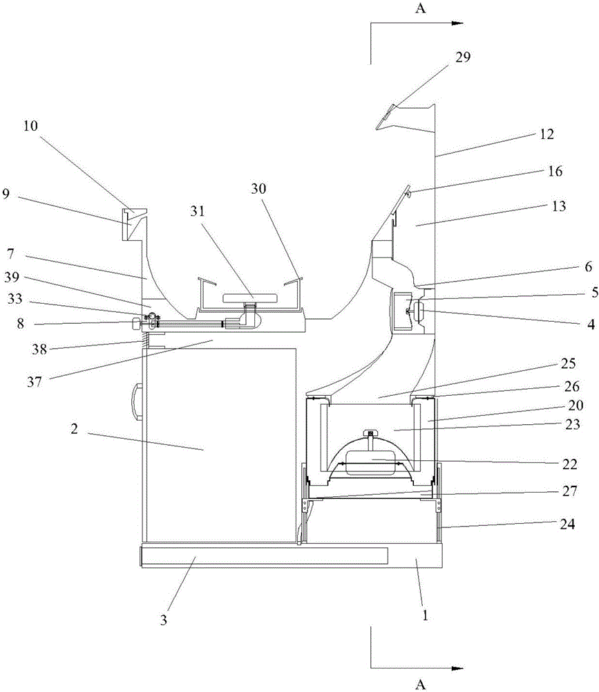
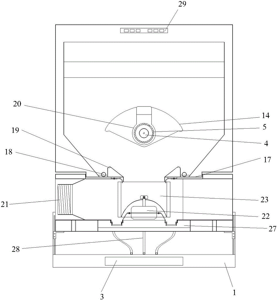
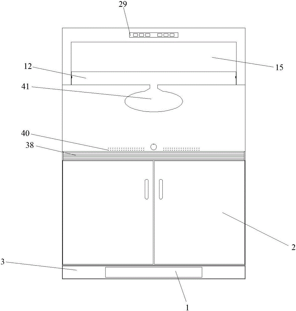
[0033] Such as Figure 1-6 As shown, the present invention includes a smoke protection and air guide mechanism, a smoke exhaust mechanism, a stove body, a locker 2 and a base 1, an oil storage box 3 is installed in a drawer type in the base 1, and the locker 2 is installed on the base 1 upper surface front.

[0034] The smoke protection and air guiding mechanism includes a blower motor 4, a blower wheel 5, a blower box 6, and a hemispherical shell 7, the hemispherical shell 7 is installed on the locker 2 with the opening facing upwards, and the hemispherical shell An air inlet passage 37 is provided between the body 7 and the locker 2, and a filter screen 38 is provided at the entrance of the air inlet passage 37. 7 outside the ignition device 8 is connected, the upper circumference of the hemispherical housing 7 is provided with an annular cavity 9, ...


PUM


Abstract

The invention discloses a smoke guiding integrated stove. The smoke guiding integrated stove comprises a smoke enclosing and air guiding mechanism, a smoke discharging mechanism and a stove body. The smoke enclosing and air guiding mechanism comprises an air supply motor, an air supply wind wheel, an air supply box body and a hemispheric shell. The stove body is arranged at the bottom of the hemispheric shell. An annular cavity is formed in the hemispheric shell. A wind guiding cover is arranged on the annular cavity. A semi-annular air outlet belt is formed between the air guiding cover and the annular cavity. Wind guiding sheets are arranged on the lower surface of the air guiding cover. The air supply box body is arranged at the rear part of the hemispheric shell and communicates with the annular cavity. The smoke discharging mechanism is arranged at the rear part of the hemispherical shell. An air inlet of the smoke discharging mechanism is opposite to a wind curtain. A wind formed by the air supply wind wheel enters the annular cavity from an air supply channel, then an upward inclined wind curtain is formed through the semi-annular air outlet belt and the wind guiding sheets, air above a range hood is difficult to enter a cooking area under the effect of the wind curtain, meanwhile, oil smoke formed by cooking is completely guided to the smoke discharging mechanism to be discharged, and therefore the energy consumption of a smoke discharging motor is reduced.

Description

technical field [0001] The invention relates to an integrated cooker, in particular to a smoke guiding integrated cooker. Background technique [0002] The oily fume in the kitchen is the biggest killer of kitchen staff and kitchen equipment. It not only makes people uncomfortable but also affects people's health. It has great damage to kitchen electrical equipment and home decoration. Therefore, it can solve kitchen oily fume more efficiently, conveniently and energy-saving. It is a difficult problem to be overcome by the broad minded people in the society. [0003] The kitchen range hoods used in the market have the following problems. First, the range hood sucks more air than oil fume. Second, the exhaust of the range hood is not clean. Breeze will cause the fumes to run out of the kitchen, and the problems that come with the use of more efficient range hoods are the increase in motor power, energy consumption and noise. With the advancement of social urbanization, more ...

Claims


Application Information

Patent Timeline
Patent Type & Authority Applications(China)
IPC IPC(8): F24C15/20A47B77/08
CPCF24C15/2042A47B77/08F24C15/2085
Inventor 彭阔羽
Owner 彭阔羽
Why Eureka
Try Eureka