
Ice producing assembly and method for controlling temperature of ice producing cavity

A temperature control method and ice cavity technology, which are applied to refrigeration components, ice making, ice making, etc. Realize the effect of simplification and increase of ice storage capacity

Active Publication Date: 2017-05-10
HEFEI HUALING CO LTD +2
View PDF8 Cites 2 Cited by
  • Summary
  • Abstract
  • Description
  • Claims
  • Application Information

AI Technical Summary

Problems solved by technology

At this time, the space where the ice maker and the ice storage box are located is completely connected, and the ice making and ice storage are in the same concave cavity, so the temperature in the ice storage box during the ice making process of the ice machine is similar to the temperature around the ice machine , and the actual required storage temperature of ice cubes is higher than the ice-making temperature, which causes the loss of cooling capacity, which in turn results in a corresponding reduction in ice-making capacity.
In addition, when the ice machine starts to heat and de-ice, the heating wire of the ice machine will work, which will cause the temperature around the ice machine to rise, causing the temperature in the ice storage box to fluctuate, affecting the storage of ice cubes

Method used


Image

  • Ice producing assembly and method for controlling temperature of ice producing cavity
  • Ice producing assembly and method for controlling temperature of ice producing cavity
  • Ice producing assembly and method for controlling temperature of ice producing cavity

Examples


Embodiment 1

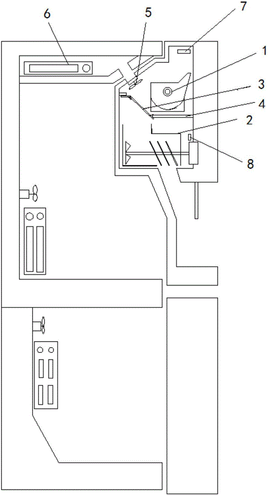
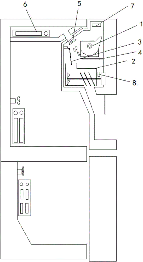
[0066] An ice-making assembly, including an ice-making chamber, an ice maker 1 installed above the inside of the ice-making chamber, and an ice storage box 2 located at the lower part inside the ice-making chamber, and also includes:

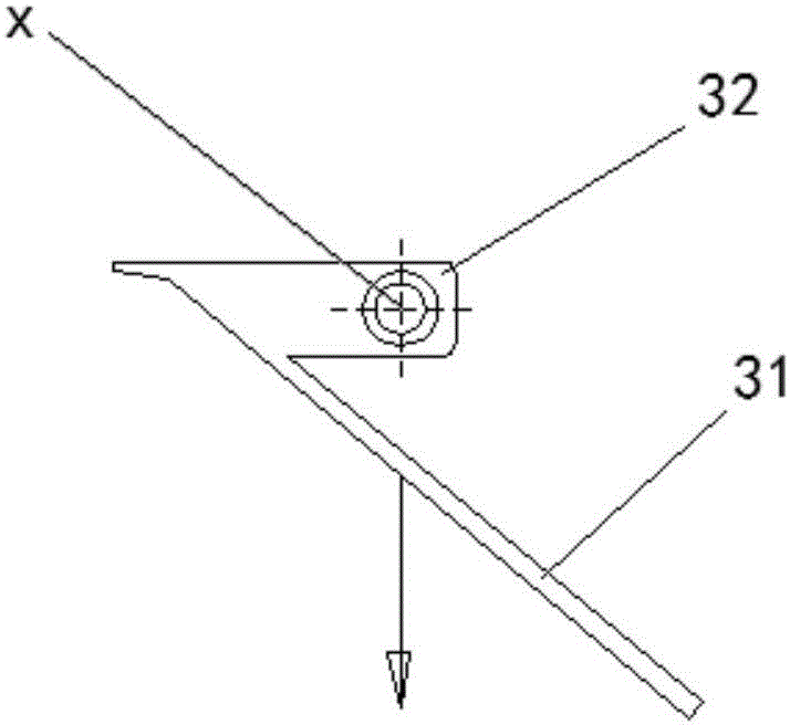
[0067] Movable partition 3, the movable partition 3 is arranged between the ice maker 1 and the ice storage box 2 for communicating or separating the ice maker 1 and the ice storage box 2, the movable partition 3 divides the ice making chamber The body is divided into two parts: the ice making area and the ice storage area;

[0068] A fan 5, the fan 5 is arranged at the opening at the upper end of the ice-making cavity, and the opening communicates with the cavity where the ice-making evaporator 6 is located and the ice-making cavity;

[0069] An ice storage area temperature sensor 8, the ice storage area temperature sensor 8 for collecting the actual temperature of the ice storage area is located at the lower part of the ice storage box and con...

Embodiment 2

[0088] An ice-making assembly, including an ice-making chamber, an ice maker 1 installed above the inside of the ice-making chamber, and an ice storage box 2 located at the lower part inside the ice-making chamber, and also includes:

[0089] Movable partition 3, the movable partition 3 is arranged between the ice maker 1 and the ice storage box 2 for communicating or separating the ice maker 1 and the ice storage box 2, the movable partition 3 divides the ice making chamber The body is divided into two parts: the ice making area and the ice storage area;

[0090] A fan 5, the fan 5 is arranged at the opening at the upper end of the ice-making cavity, and the opening communicates with the cavity where the ice-making evaporator 6 is located and the ice-making cavity;

[0091] An ice-making zone temperature sensor 7, the ice-making zone temperature sensor 7 for collecting the actual temperature of the ice-making zone is located above the ice maker 1 and connected to the inner wa...

Embodiment 3

[0111] Such as Figure 1-3 As shown, an ice-making assembly includes an ice-making cavity, an ice maker 1 installed above the inside of the ice-making cavity, and an ice storage box 2 located at the lower part of the inside of the ice-making cavity, and also includes:

[0112] Movable partition 3, the movable partition 3 is arranged between the ice maker 1 and the ice storage box 2 for communicating or separating the ice maker 1 and the ice storage box 2, the movable partition 3 divides the ice making chamber The body is divided into two parts: the ice making area and the ice storage area;

[0113] A fan 5, the fan 5 is arranged at the opening at the upper end of the ice-making cavity, and the opening communicates with the cavity where the ice-making evaporator 6 is located and the ice-making cavity;

[0114] An ice storage area temperature sensor 8, the ice storage area temperature sensor 8 for collecting the actual temperature of the ice storage area is located at the lower...


PUM


Abstract

The invention relates to an ice producing assembly, which comprises an ice producing cavity, an ice producing machine arranged in the upper part of the interior of the ice producing cavity, and an ice storage box arranged in the lower part of the interior of the ice producing cavity. The ice producing assembly also comprises a movable partition plate, which is arranged between the ice producing machine and the ice storage box and is used to communicate / partition the ice producing machine and the ice storage box; a fan, which is arranged in the opening in the upper end of the ice producing cavity; an ice storage area temperature sensor, which is arranged in the lower part of the ice storage box, is connected to the inner wall of the ice storage box, and is used to collect the actual temperature of the ice storage area; and a microprocessor, which is connected to the ice storage area temperature sensor, receives the actual temperature collected by the ice storage area temperature sensor, is connected to the fan, and controls the operation mode of the fan. The ice producing assembly has the advantages that the ice producing area and the ice storage area are separated; the energy loss is reduced, the ice output is increased, and the temperature can be simply controlled.

Description

technical field [0001] The invention relates to the field of refrigeration equipment, in particular to an ice-making assembly and a method for controlling the temperature of an ice-making cavity. Background technique [0002] The ice machine in the prior art is generally installed on the back of the door, and the ice storage box (ice storage bucket) is directly placed under the ice machine. When the ice machine is full of ice, the ice cubes directly fall into the ice storage. in the box. At this time, the space where the ice maker and the ice storage box are located is completely connected, and the ice making and ice storage are in the same concave cavity, so the temperature in the ice storage box during the ice making process of the ice machine is similar to the temperature around the ice machine , and the actual required storage temperature of ice cubes is higher than the ice-making temperature, which results in a loss of cooling capacity and a corresponding reduction in ...

Claims


Application Information

Patent Timeline
IPC IPC(8): F25C1/00F25B49/00
CPCF25B49/00F25C1/00
Inventor 邵阳司增强
Owner HEFEI HUALING CO LTD
Learn More