

Heat exchange device for sludge carbonization technology
A heat exchange device and heat exchanger technology, applied in the direction of heat exchanger types, indirect heat exchangers, lighting and heating equipment, etc., can solve the problems of poor heat exchange effect and heat exchange efficiency, and improve heat exchange efficiency. Effect
- Summary
- Abstract
- Description
- Claims
- Application Information
AI Technical Summary
Problems solved by technology
Method used
Image

Examples
Embodiment Construction
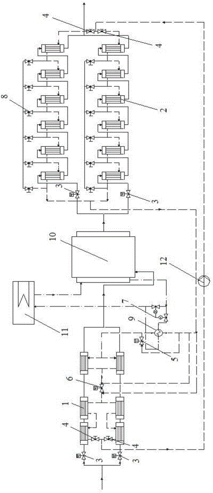
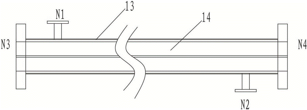
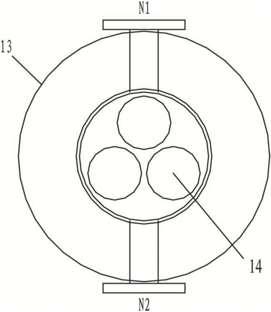
[0022] In order to understand the above-mentioned purpose, features and advantages of the present invention more clearly, the present invention will be further described in detail below in conjunction with the accompanying drawings and specific embodiments. It should be noted that, in the case of no conflict, the embodiments of the present application and the features in the embodiments can be combined with each other.
[0023] In the description of the present invention, it should be noted that the terms "center", "longitudinal", "transverse", "upper", "lower", "front", "rear", "left", "right", " The orientations or positional relationships indicated by "vertical", "horizontal", "top", "bottom", "inner" and "outer" are based on the orientations or positional relationships shown in the drawings, and are only for the convenience of describing the present invention and Simplified descriptions, rather than indicating or implying that the device or element referred to must have a ...
PUM
 Abstract
Description
Claims
Application Information