Terahertz image non-uniformity correction method

A non-uniformity correction, terahertz technology, applied in the field of terahertz imaging, can solve the problems affecting the non-uniformity correction results of terahertz detectors, image distortion, etc., to achieve accurate response and ensure the effect of imaging effects

Inactive Publication Date: 2017-05-10
UNIV OF ELECTRONIC SCI & TECH OF CHINA
View PDF15 Cites 8 Cited by
  • Summary
  • Abstract
  • Description
  • Claims
  • Application Information

AI Technical Summary

Problems solved by technology

[0005] The size of the focal plane array and the response of each unit should be fully considered in the non-uniformity correction of the terahertz image. However, since the terahertz light source is a point source, the detector usually receives the terahertz radiation locally, and the local Terahertz radiation can affect the non-uniformity correction results o

Method used


Image

  • Terahertz image non-uniformity correction method
  • Terahertz image non-uniformity correction method
  • Terahertz image non-uniformity correction method

Examples


Embodiment Construction

[0043]The specific embodiments of the present invention are further described in conjunction with the following drawings. The embodiments here are only used to illustrate the present invention, but are not used to limit the protection scope of the present invention.

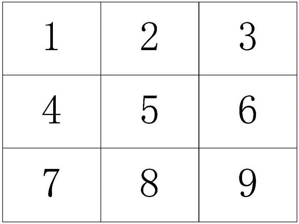
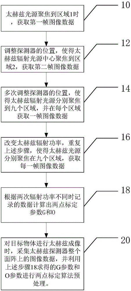
[0044] figure 1 It is a schematic diagram of the area division of the terahertz detector array of a specific embodiment of the present invention, from figure 1 It can be seen that in this embodiment, the terahertz detector area array is divided into 9 regions according to the division method of 3×3. According to the knowledge of those skilled in the art, the division method of regions is not limited to the division method of this embodiment , as long as each area does not overlap after division and includes the entire area array of the detector; figure 2 It is a schematic diagram of the non-uniformity correction process of the terahertz image obtained by using this division method embodiment. Such as figure ...


PUM


Abstract

The invention discloses a terahertz image non-uniformity correction method, and relates to the terahertz imaging technology field. Defects caused by incomplete response of a part of detection units during acquisition of terahertz image data are effectively overcome. A terahertz detector area array is divided into a plurality of areas to acquire a response gain parameter and an offset parameter, which are more accurate, and are used for two-point calibration algorithm pretreatment of a terahertz image of a target object, and then a final correction parameter can be used to reflect the response conditions of the various detection units of the detector area array accurately, and therefore better image effect can be acquired, and an image distortion problem caused by unreasonable weight allocation is overcome. The terahertz image non-uniformity correction method further comprises one-point calibration algorithm pretreatment used for updating the offset parameter, and therefore an object of real-time correction of response output of an imaging system is achieved. The temperature drift phenomenon of the terahertz array detector imaging system in a working state is overcome.

Description

technical field [0001] The invention relates to the technical field of terahertz imaging, in particular to a method for correcting non-uniformity of terahertz images. Background technique [0002] Terahertz imaging is a hot technology in current research. The main reason is that terahertz radiation has low photon energy and high penetration ability to non-metal and non-polar substances, making it able to penetrate clothes, plastics, ceramics, etc. Therefore, it shows great application prospects in non-destructive testing, medical inspection, safety testing, environmental monitoring and space remote sensing. [0003] Due to factors such as its manufacturing process, external environment, and optical imaging of the terahertz detector, the original image output by the detector will more or less have defects such as misalignment, response non-uniformity, and blind pixels. Therefore, the preprocessing of the original image is very necessary. [0004] The preprocessing of the or...

Claims


Application Information

Patent Timeline
IPC IPC(8): G01J3/28
CPCG01J3/2823G01J2003/2866
Inventor 郑兴余段辉张鸿波李成世熊兴赵嘉学
Owner UNIV OF ELECTRONIC SCI & TECH OF CHINA
Why Eureka
Try Eureka