Novel power lateral confinement compression test device

A technology of confining compression and testing device, applied in measuring device, testing material strength by applying repetitive force/pulse force, testing material strength by applying stable tension/pressure, etc., can solve the problem of heavy weight, foundation settlement, operation Inconvenience and other problems, to achieve the effect of accurate measurement of test data

Pending Publication Date: 2017-05-10
WUHAN UNIV OF SCI & TECH
View PDF8 Cites 8 Cited by
  • Summary
  • Abstract
  • Description
  • Claims
  • Application Information

AI Technical Summary

Problems solved by technology

But as we all know, in the real environment, the load on the upper part of the soil is not always a static load. Impact rolling, vehicle moving traffic load on the upper part of the roadbed, oil storage tank liquid level rises and falls repeatedly, these are all dynamic loads, the loads on the foundation in these places are all dynamic loads, and the existing conventional geotechnical test devices cannot complete dynamic loading, and cannot Simulate dynamic complex situations in engineering practice
In addition, environmental loads, such as seaside and coastal areas, due to tidal effects, water level fluctuations will also cause foundation settlement. It can be seen that the effect of environmental hydrodynamics on the foundation also needs to be considered; at the same time, in some areas with frequent rainfall and evaporation, due to dry The change of the properties of the soil itself due to the wet cycle ...

Method used


Image

  • Novel power lateral confinement compression test device
  • Novel power lateral confinement compression test device
  • Novel power lateral confinement compression test device

Examples


specific Embodiment approach

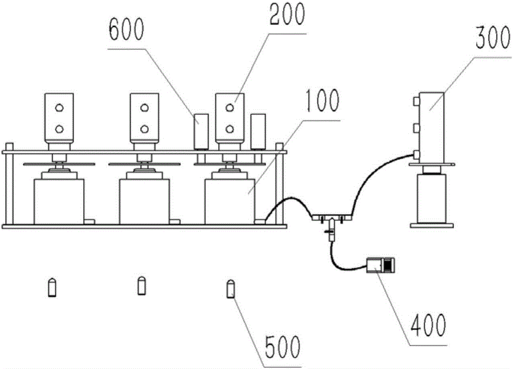
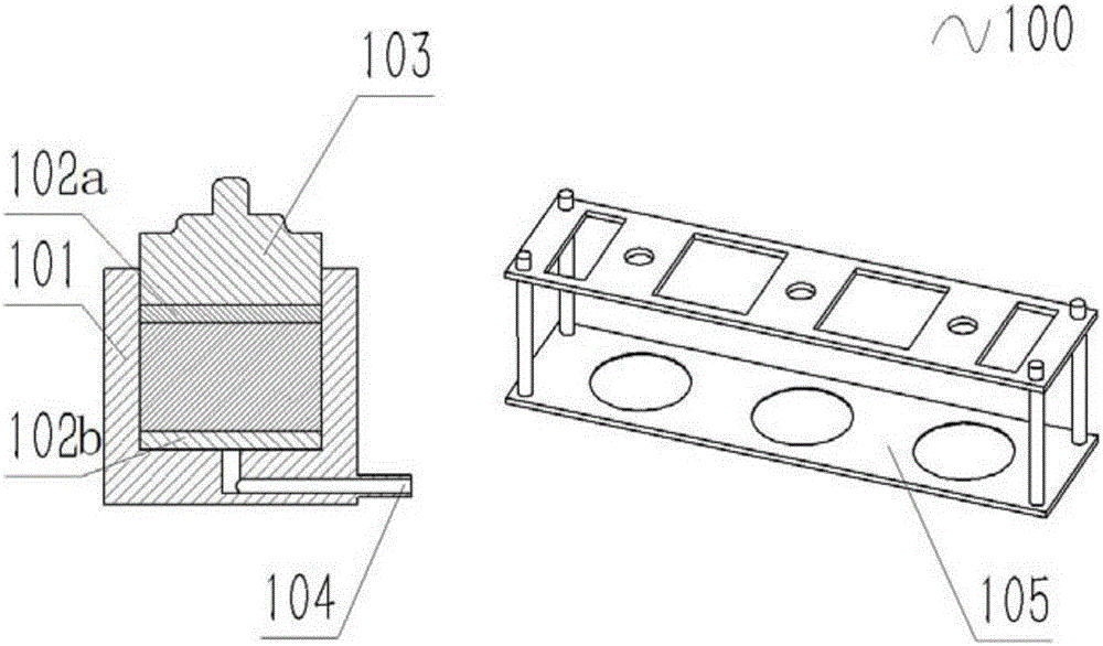
[0047] The specific implementation is as follows: the air pressure system 210 provides a power source, and is applied to the permeable stone 102 and the sample through the loading cover 103; the air pressure circuit control system controls the loading mode, application size and application time; Load Connection Mode and Cyclic Static Pressure Load Connection Mode Three gas circuit connection modes can apply impact load, constant static pressure load and cyclic static pressure load to the sample.

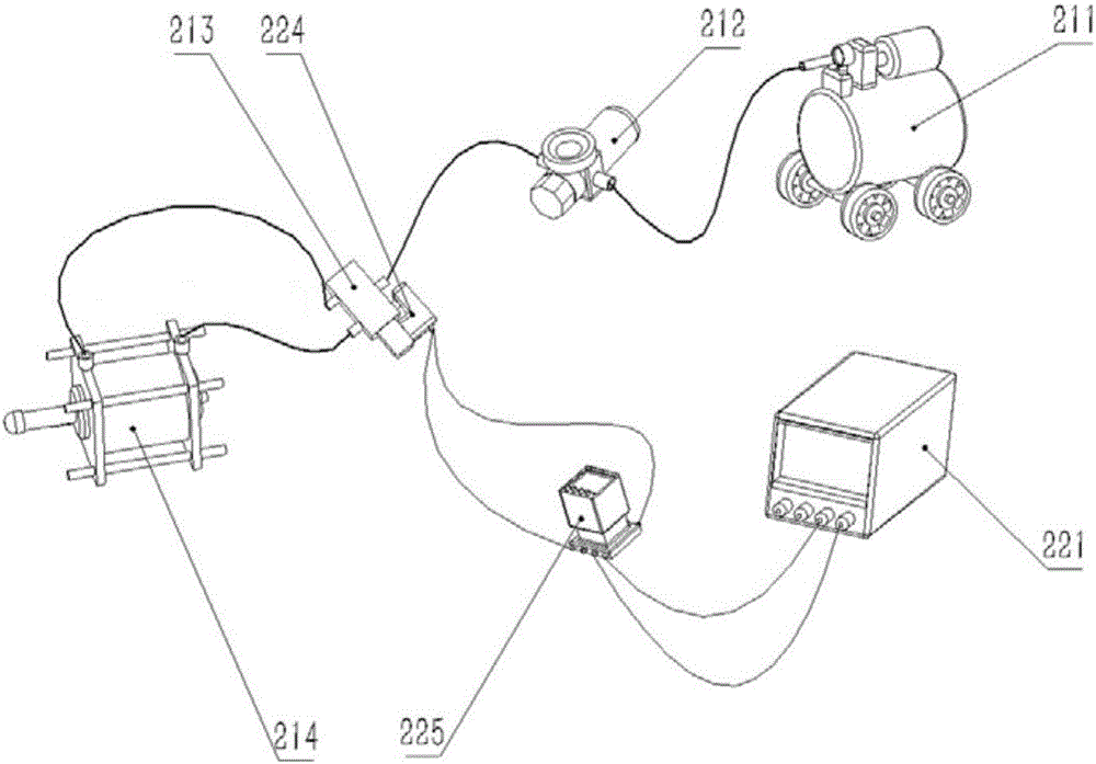
[0048] Wherein, when the load of the vertical load loading module 200 is an impact dynamic load, such as image 3 The specific structure shown is: including a DC power supply 221 connected in sequence, a time relay 225 and a solenoid valve 224 connected in sequence in a circuit; 214 , the solenoid valve 224 is installed on the cylinder switch 213 for controlling the cylinder switch 213 , and the cylinder 214 is connected to the top of the compressor 100 . The working principle of th...


PUM


Abstract

The invention provides a novel power lateral confinement compression test device. The novel power lateral confinement compression test device comprises a compression apparatus and a displacement measuring module, wherein the displacement measuring module is used for monitoring the position change of a sample. The novel power lateral confinement compression test device is characterized by also comprising a vertical load loading module, a water level fluctuating module, a dry and wet circulating module and a sample deformation monitoring module; the vertical load loading module is arranged at the top part of the compression apparatus, and is used for providing a vertical load for the sample; the water level fluctuating module is connected with one side of the compression apparatus, and is used for simulating a tide load; the dry and wet circulating module is connected with the bottom part of the compression apparatus, and is used for simulating rainfall and evaporation; the sample deformation monitoring module is arranged at the side of the compression apparatus, and is used for observing and recording the deformation of the sample in the experiment process. The novel power lateral confinement compression test device has the advantages that in a lateral confinement compression test, multiple power loads can be loaded to the sample, the complicated conditions in the project practice are simulated, the soil stress state is truly reflected, and the change of compression characteristic of the soil under the action of external load is measured.

Description

technical field [0001] The invention belongs to the field of geotechnical engineering, and in particular relates to a novel dynamic confinement compression test device. Background technique [0002] Confined compression test is a common content in geotechnical tests. Through confining compression test, the compressibility of soil is measured, and it is used to analyze the settlement of building foundations and roadbeds. The conventional method of confining compression test is to put the soil in a fixed-volume steel container, cover the upper part of the soil with a steel pressure plate, and amplify the structure through a force arm composed of weights and levers, and apply static pressure to the pressure plate on the soil. The pressure, and the compression deformation of the soil is analyzed by measuring equipment such as a dial gauge, which has the characteristics of a simple structure. But as we all know, in the real environment, the load on the upper part of the soil is ...

Claims


Application Information

Patent Timeline
IPC IPC(8): G01N3/12G01N3/307G01N3/36
CPCG01N3/12G01N3/307G01N3/36G01N2203/001G01N2203/0005G01N2203/0003G01N2203/0019G01N2203/0044
Inventor 王帅雷学文董云洁孟庆山张中信徐亚飞李雨杰周疆豪李昇昊卫一丰龚屿
Owner WUHAN UNIV OF SCI & TECH
Why Eureka
Try Eureka