Voltage transformer insulation sleeve tube monitoring device and installation method therefor
A technology for monitoring equipment and insulating bushings, applied in the direction of measuring devices, measuring device casings, instruments, etc., can solve problems affecting monitoring work, insulation breakdown, equipment damage, etc.
- Summary
- Abstract
- Description
- Claims
- Application Information
AI Technical Summary
Problems solved by technology
Method used
Image
Examples
Embodiment 1
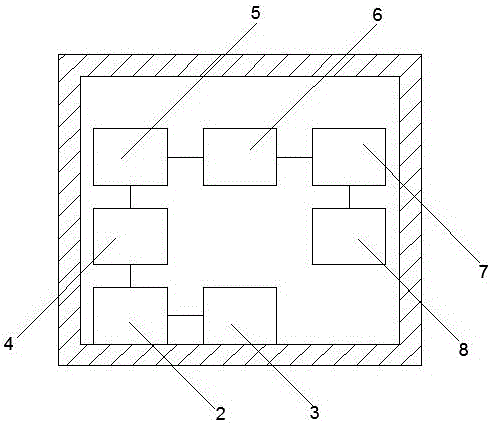
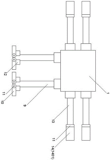
[0018] Such as figure 1 and figure 2 The transformer insulating bushing monitoring equipment shown includes a monitoring equipment casing 1, and the casing of the monitoring equipment is equipped with a bushing end screen adapter 2, an end screen grounding wire 3, a flow measurement module 4, and an online monitoring and merging unit 5. On-line monitoring of IED6, voltage transformer merging unit 7 and transmission optical cable 8; the bottom end and side ends of the monitoring equipment housing 1 are respectively provided with a bottom fixing device and a side fixing device; the bottom fixing device includes There is a support rod 9 extending in the vertical direction, which adopts an electric screw structure. Two fixed end plates 10 are arranged at the bottom of the support rod 9, and each fixed end plate 10 and the support rod 9 pass through The rotating shaft 11 is connected, and the rotating shaft 11 of each fixed end plate 10 is provided with a fixed motor 12 for drivi...
Embodiment 2
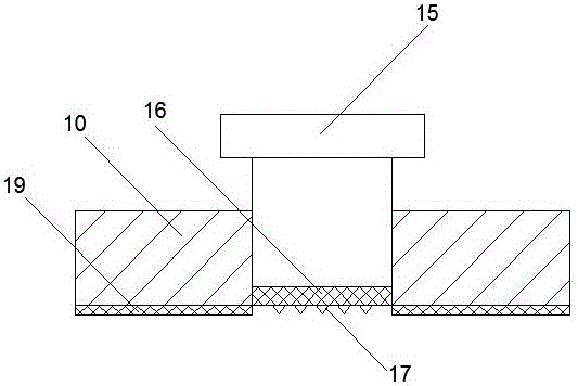
[0021] As an improvement of the present invention, such as image 3 As shown, the bottom end surface of the fixed end plate 10 is provided with a rubber anti-skid layer 19, which can improve the friction effect of the fixed end plate relative to the ground, and thus improve the overall support stability of the transformer insulating bushing monitoring equipment. further improvements.
[0022] The remaining features and advantages of this embodiment are the same as those of Embodiment 1.
Embodiment 3
[0024] As an improvement of the present invention, such as image 3 As shown, each fixed end plate 10 is provided with a fastening screw hole, and a fastening bolt 15 is arranged in the fastening screw hole, and a fastening end body 16 is arranged on the bottom surface of the fastening bolt 15. Made of rubber, the bottom end surface of the fastening end body 16 is provided with a plurality of downwardly extending conical bodies 17 . With the above-mentioned technical scheme, after the fixed end plate is placed well, it can form a downward pressure in the vertical direction through the fastening bolts, so that the fastening end body and the cone body at the end can be fixed relative to the soft ground surface. The degree of pressing and engaging treatment further improves the installation stability of the fixed end plate relative to the soft ground.
[0025] The remaining features and advantages of this embodiment are the same as those of Embodiment 2.
PUM
 Abstract
Description
Claims
Application Information
 - R&D
- Intellectual Property
- Life Sciences
- Materials
- Tech Scout
- Unparalleled Data Quality
- Higher Quality Content
- 60% Fewer Hallucinations
Browse by: Latest US Patents, China's latest patents, Technical Efficacy Thesaurus, Application Domain, Technology Topic, Popular Technical Reports.
© 2025 PatSnap. All rights reserved.Legal|Privacy policy|Modern Slavery Act Transparency Statement|Sitemap|About US| Contact US: help@patsnap.com


