Power detection circuit for switching power supply

A technology of power detection circuit and switching power supply, which is applied in the direction of electric power measurement through current/voltage, measurement of current/voltage, measurement device, etc., which can solve the problem of increasing manufacturing costs, the inability to accurately detect tiny currents, and the inability to measure micro-power Power consumption of components and other issues

Inactive Publication Date: 2017-05-10
UNIV OF SHANGHAI FOR SCI & TECH
View PDF7 Cites 8 Cited by
  • Summary
  • Abstract
  • Description
  • Claims
  • Application Information

AI Technical Summary

Problems solved by technology

However, there are three problems in the switching power supply power detection circuit used today: 1. The power detection circuit is mainly realized by a power meter, and rarely detects current and voltage at the same time; 2. The current sensor used in the power detection circuit cannot detect the tiny current. Accurate detection; 2. Most power detection circuits use current or voltage sensors, which greatly increases the manufacturing cost
[0003] When using a power meter to measure the power of the switching power supply, since the power meter can only test the power of the whole product, limited by the current measurement range, it is impossible to measure the power of micro-power components
When a large system fails, it is impossible to find out the fault point and di

Method used


Image

  • Power detection circuit for switching power supply
  • Power detection circuit for switching power supply
  • Power detection circuit for switching power supply

Examples


Embodiment

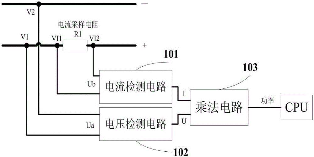
[0027] figure 1 It is a schematic diagram of the circuit structure of the switching power supply power detection circuit in the embodiment of the present invention.

[0028] Such as figure 1 As shown, the switching power supply power detection circuit includes a current sampling resistor R1 , a current detection circuit 101 , a voltage detection circuit 102 , and a multiplication circuit 103 . In this embodiment, the output end of the multiplication circuit 103 is connected to the CPU of the computer.

[0029] The current sampling resistor R1 is used to form the sampling current.

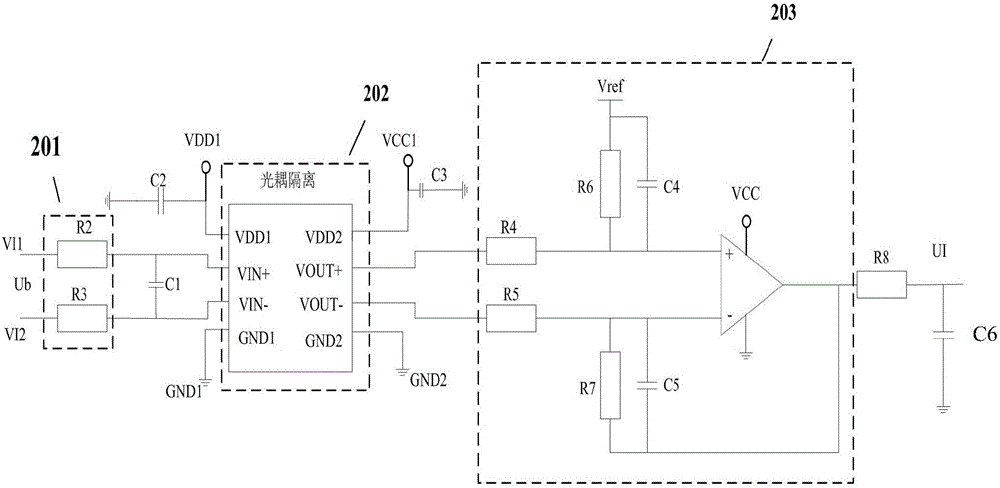
[0030] The current detection circuit 101 is used to detect the current value of the part to be tested on the circuit board.

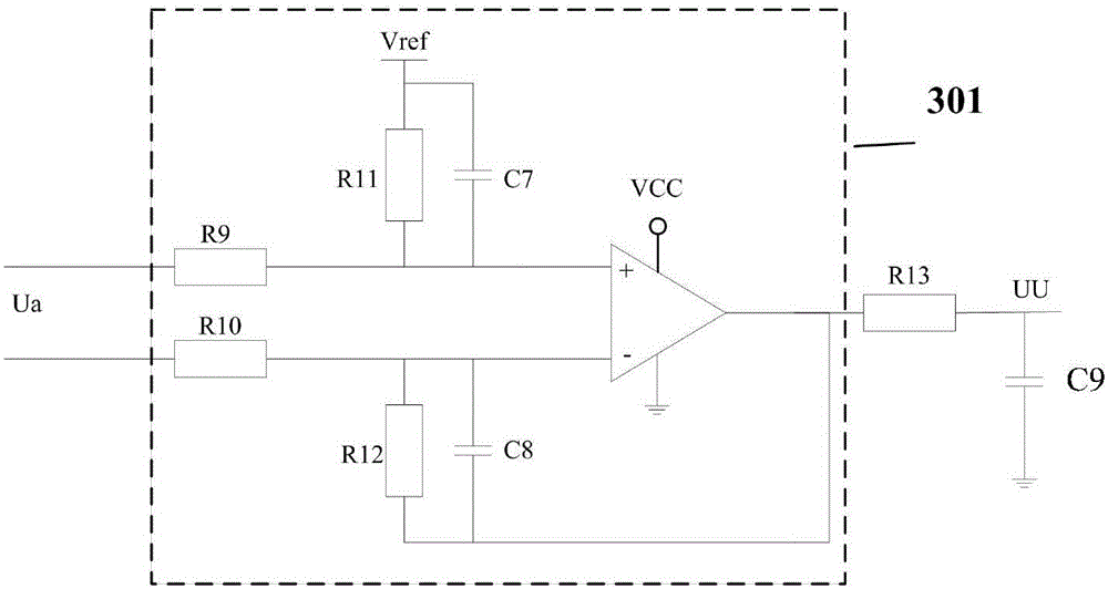
[0031] The voltage detection circuit 102 is used to detect the voltage value of the part to be tested on the circuit board.

[0032] The multiplication circuit 103 is used to multiply the detected current and voltage to achieve the purpose of power detection.

[0033] ...


PUM


Abstract

The invention discloses a power detection circuit for a switching power supply, and the circuit is disposed on a power line. The power line is provided with at least one current sampling resistor. The circuit comprises a current detection circuit which is provided with a current sampling end and a current output end in parallel connection with the current sampling resistor and is used for detecting the value of a current in the power line; a voltage detection circuit which is provided with a voltage sampling end and a voltage output end, which are in connection with a positive electrode and a negative electrode, and is used for detecting the value of a voltage in the power line; and a multiplying circuit which is connected with the current output end and the voltage output end, enables the detected current and voltage to be multiplied, and outputs the power value. The current detection circuit comprises a first current-limiting resistor, a decoupling capacitor, an optical coupled isolator and a first differential amplification circuit, wherein the first current-limiting resistor, the decoupling capacitor, the optical coupled isolator and the first differential amplification circuit are connected sequentially. The voltage detection circuit comprises a second differential amplification circuit. The voltage measurement value and the current measurement value are multiplied through the multiplying circuit, thereby obtaining the power. The whole power detection circuit is precise in voltage detection, is small in operation current, and is low in cost.

Description

technical field [0001] The invention belongs to the field of power detection and relates to a power detection circuit for detecting current, voltage and power of the output of a switching power supply. Background technique [0002] At present, switching power supplies are widely used in the electrical industry, especially in the field of power electronics technology. When using a switching power supply, the power of the switching power supply is detected, and the output of current and voltage is constantly grasped to facilitate the diagnosis and maintenance of the equipment and avoid unnecessary emergencies. However, there are three problems in the switching power supply power detection circuit used today: 1. The power detection circuit is mainly realized by a power meter, and rarely detects current and voltage at the same time; 2. The current sensor used in the power detection circuit cannot detect small currents. Accurate detection; 2. Most power detection circuits use cu...

Claims


Application Information

Patent Timeline
IPC IPC(8): G01R21/06G01R19/00
CPCG01R21/06G01R19/00
Inventor 陈青熊蒙
Owner UNIV OF SHANGHAI FOR SCI & TECH
Why Eureka
Try Eureka