
Water flow control system

A water flow control and water flow technology, which is applied in the direction of electrical program control, sequence/logic controller program control, etc., can solve the problems of water consumption, time consumption, and shortened service life.

Inactive Publication Date: 2017-05-10
张广威
View PDF5 Cites 2 Cited by
  • Summary
  • Abstract
  • Description
  • Claims
  • Application Information

AI Technical Summary

Problems solved by technology

[0004] The technical problem to be solved by the present invention is to provide a water flow control system, which effectively solves the above-mentioned existing problems of inconvenient operation, water-consuming, time-consuming, and shortened service life of the existing garbage disposal shredder when used in the water flow.

Method used


Image

  • Water flow control system
  • Water flow control system

Examples


specific Embodiment approach 1

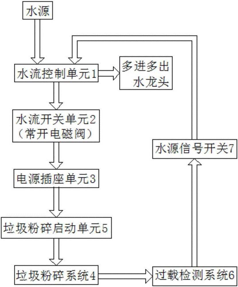
[0021] like figure 1 As shown, a water flow control system includes a water flow control unit 1, and the water flow control unit 1 adopts a faucet, wherein the faucet adopts multi-input and multiple-outlet (for example: a dual-temperature water outlet faucet, two of which are dual-temperature water outlets, One of them is a dedicated control device of the water flow control unit 1);

[0022] The water flow switch unit 2 controls the power socket unit 3 and the main power supply to be powered on and off, wherein the water flow switch unit 2 adopts a normally open solenoid valve, and when the water flow in the pipeline is directional, the contact of the solenoid valve is touched to make it closed, and then Connecting the water flow switch unit 2 means that the power socket unit 3 and the main power supply are energized; when the water flow stops, the water flow thrust disappears, so the water flow switch unit 2 (normally open solenoid valve) resets and powers off, realizing the ...

specific Embodiment approach 2

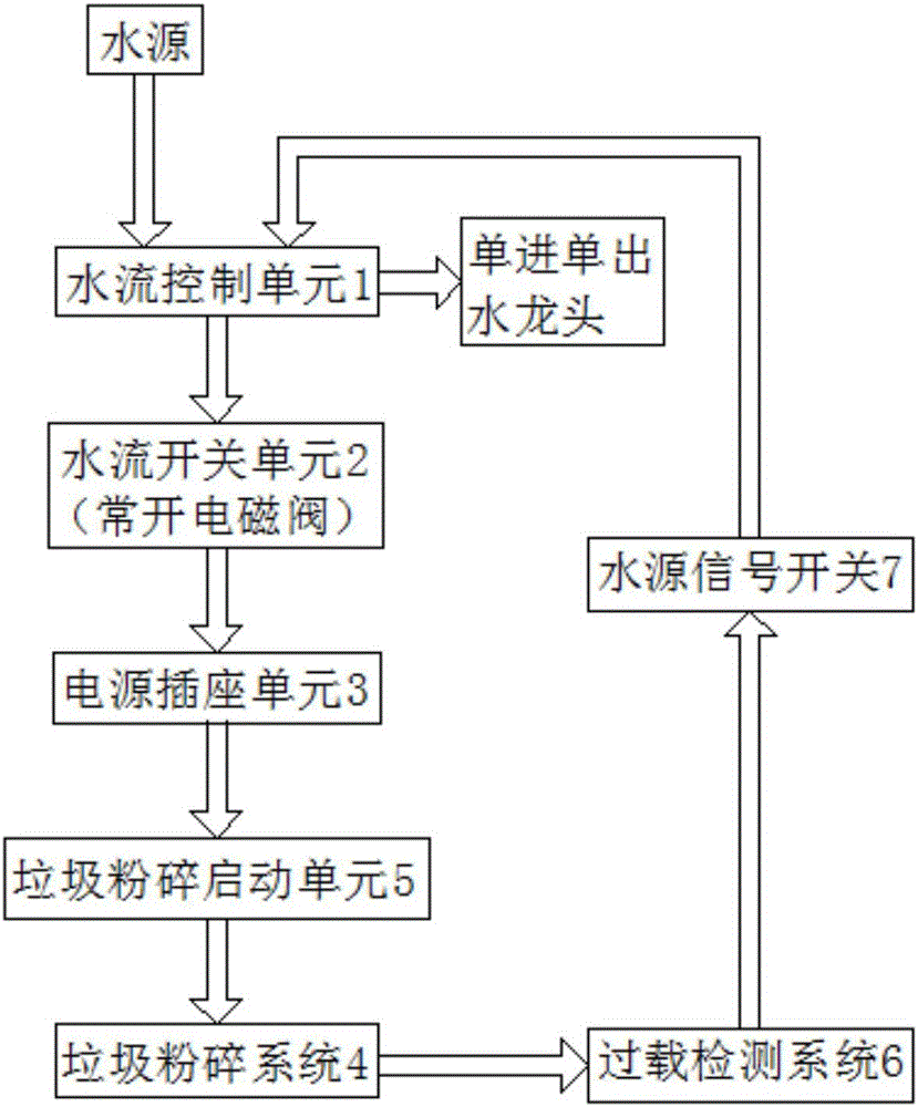
[0028] like figure 2 As shown, the water flow control unit 1 also includes a single-inlet and single-outlet faucet, which is used as a dedicated control device for the water flow control unit 1 .

[0029] The rest are as in the first embodiment, which will not be repeated here.

[0030] When the control system is started, the water flow control unit 1 (faucet) can be turned on, and the water flow force can make the water flow switch unit 2 (normally open solenoid valve) close, and then the power socket unit 3 and the main power supply can be automatically energized; The conductor makes the main body of the power socket unit 3 conductive, and then the garbage shredding starting unit 5 activates the garbage shredding system 4, so as to clean up the garbage.

[0031] When the garbage cleaning work is overloaded, the overload detection system 6 is started, and then the water flow control unit 1 (water tap) is closed through the water source signal switch 7 . Because the water f...


PUM


Abstract

The invention discloses a water flow control system, comprising a water flow control unit; the control system further comprises a water flow switch unit, a power socket unit and a garbage crushing system, wherein the water flow switch unit controls on and off of the power socket unit and a main power supply, the power socket unit controls the working states of connection and disconnection of a power socket unit body, and the garbage crushing system is used for crushing garbage; the water flow control unit is opened to urge power-on start of the water flow switch unit so that the power socket unit is connected to the main power supply, passing water flow serving as a conductor is connected to the power socket unit body, the power socket unit is in a turn-on working state, and then the garbage crushing system is started. The control system can realize full-automatic operation from starting a water source, connecting to power and starting a garbage crusher, the power-on safety is further ensured via an overload detection system, and the control system is energy-saving, environment-friendly and simple in operation, guarantees the safety and prolongs the service life of the garbage crusher.

Description

technical field [0001] The invention relates to the supporting application field of power supply control of electrical equipment, is applicable to simultaneous electricity and water environments, a hydropower and water flow control system, and specifically relates to a water flow control system. Background technique [0002] At present, the country pays more and more attention to the home environment, from safety and comfort to environmental protection and sanitation, and a product such as garbage disposer was born accordingly. The food waste generated before and after cooking can be crushed into granules by the existing food waste shredder under the sink and taken away by the water flow. On the one hand, the family hygiene environment can be improved to avoid the breeding of bacteria; on the other hand, the food waste can be washed away by the water flow of the underground pipeline , is treated uniformly by the sewage treatment plant, which avoids the secondary garbage poll...

Claims


Application Information

Patent Timeline
Patent Type & Authority Applications(China)
IPC IPC(8): G05B19/04
CPCG05B19/04
Inventor 张广威
Owner 张广威
Learn More