
Passive temperature measuring electronic name plate based on RFID technology

An electronic and nameplate technology, applied in the field of passive temperature measurement electronic nameplate, can solve the problems of high installation and maintenance cost, property loss, affecting production and work progress, etc. Effect

Pending Publication Date: 2017-05-10
SHENZHEN GENRACE TECH
View PDF9 Cites 0 Cited by
  • Summary
  • Abstract
  • Description
  • Claims
  • Application Information

AI Technical Summary

Problems solved by technology

For example, in the fields of production, electric power, instrumentation and other fields, it is necessary to monitor the temperature of the equipment. If the temperature exceeds the normal range due to equipment failure or external factors, it will cause equipment damage, property loss, and affect production and work progress.
[0004] At present, the nameplate is mainly based on physical identification, and the nameplate with temperature sensing is still in the blank stage. The current temperature measurement method is mostly active, although the purpose of temperature measurement can be achieved, but the volume is large, and the installation and maintenance costs are high.

Method used


Image

  • Passive temperature measuring electronic name plate based on RFID technology
  • Passive temperature measuring electronic name plate based on RFID technology
  • Passive temperature measuring electronic name plate based on RFID technology

Examples


Embodiment Construction

[0022] The embodiments of the present invention will be described in detail below with reference to the accompanying drawings, but the present invention can be implemented in many different ways defined and covered by the claims.

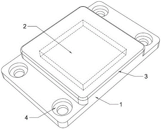
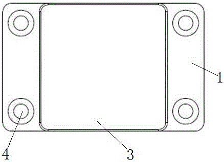
[0023] Such as figure 1 and combine figure 2 and image 3 As shown, a passive temperature measurement electronic nameplate based on RFID technology includes a bottom base 1, a passive electronic temperature measurement module 2 and a top cover layer 3, and the passive electronic temperature measurement module 2 is installed on the bottom base 1 The top cover layer 3 covers the upper end of the passive electronic temperature measurement module 2 at the middle position of the upper end surface of the upper end surface.

[0024] Further, the left and right sides of the bottom base 1 are provided with four mutually symmetrical screw fixing holes 4, the connection between the base base 1 and the passive electronic temperature measurement module 2 is p...


PUM

PropertyMeasurementUnit
thicknessaaaaaaaaaa
lengthaaaaaaaaaa
widthaaaaaaaaaa

Abstract

The invention relates to the field of electronic name plates, in particular to a passive temperature measuring electronic name plate based on the RFID technology. The passive temperature measuring electronic name plate comprises a base at the bottom, a passive electronic temperature-measuring module and a cover on the top; the passive electronic temperature-measuring module is mounted in the middle of the upper end face of the base at the bottom; and the cover on the top covers the upper end of the passive electronic temperature measuring module. The passive temperature measuring electronic name plate based on the RFID technology has the advantages that later maintenance cost is omitted as the electronic name plate utilizes the wireless and passive technology; since the electronic name plate utilizes the electronic identification technology, visual identification is omitted, and identification of the electronic name plate is not affected by abrasion of the surfaces of the electronic name plate; the RFID technology is featured by unique electronic identification, long identification distance and high identification speed; the passive electronic temperature-measuring module is of small size, so that size of the passive temperature-measuring electronic name plate is equal to that of the conventional name plate, and upgrading and updating of the name plate cannot be affected by the dimension; as the name plate is integrated with physical identification, RFID anti-metallic electronic identification and temperature sensing, equipment management and temperature monitoring are both achieved, and the name plate has high practicably.

Description

technical field [0001] The invention relates to the field of electronic nameplates, in particular to an electronic nameplate for passive temperature measurement based on RFID technology. Background technique [0002] Electronic tags are the main components of RFID (Radio Frequency Identification System) and the information carrier of the Internet of Things. With the development of radio frequency identification technology, various types of electronic tags working in the UHF frequency band (840MHz-960MHz) are increasingly used in logistics management, warehouse management, asset management and other fields. [0003] With the development of technology, the role of the nameplate has been further deepened. It not only requires the nameplate to have physical identification information such as manufacturer's trademark identification, brand distinction, and product parameters, but also develops in the direction of equipment management and temperature monitoring. For example, in th...

Claims


Application Information

Patent Timeline
Patent Type & Authority Applications(China)
IPC IPC(8): G09F9/00G06K7/10G01K13/00
CPCG06K7/10405G09F9/00G01K13/00
Inventor 许爱军
Owner SHENZHEN GENRACE TECH
Learn More