Display panel driving method and display panel

A driving method and display panel technology, applied in static indicators, instruments, etc., can solve problems such as high power consumption, save power consumption, and reduce the number of positive and negative polarity switching.

Inactive Publication Date: 2017-05-10
XIAMEN TIANMA MICRO ELECTRONICS
View PDF7 Cites 10 Cited by
  • Summary
  • Abstract
  • Description
  • Claims
  • Application Information

AI Technical Summary

Problems solved by technology

And if image 3 As shown, when the display signal 301 is applied to each pixel R, G, and B in the display panel, the display effect of using dot inversion is better, that is, the positive value of the display signal loaded by two adjacent pixels in each row or column is The negative polarity is different, but the data line 302 needs to be loaded with the display signal 301 that constantly changes in positive and negative polarity, and the power consumption is relatively large

Method used


Image

  • Display panel driving method and display panel
  • Display panel driving method and display panel
  • Display panel driving method and display panel

Examples


Embodiment 1

[0035] In this embodiment, the gate drive circuit adopts a unilateral drive mode, that is, the multiple shift registers included in the gate drive circuit are set on the same side of each gate line, that is, they can be set only on the left side of each gate line at the same time. or the right side, or only on the upper side or the lower side of each grid line at the same time.

[0036] Specifically, the shift registers can be divided into N groups, and each shift register in each group of shift registers is respectively connected to gate lines at an interval of N-1 rows; N is an integer greater than 1; that is, each shift register in each group The shift registers are set alternately. For example Figure 6 As shown, when N is 2, the shift registers are divided into two groups, among which the shift registers SR1, SR3... of the first group of shift registers VSR are all connected to the same clock control signal terminal CKV1, CKV2, and the group VSR The first-stage shift re...

Embodiment 2

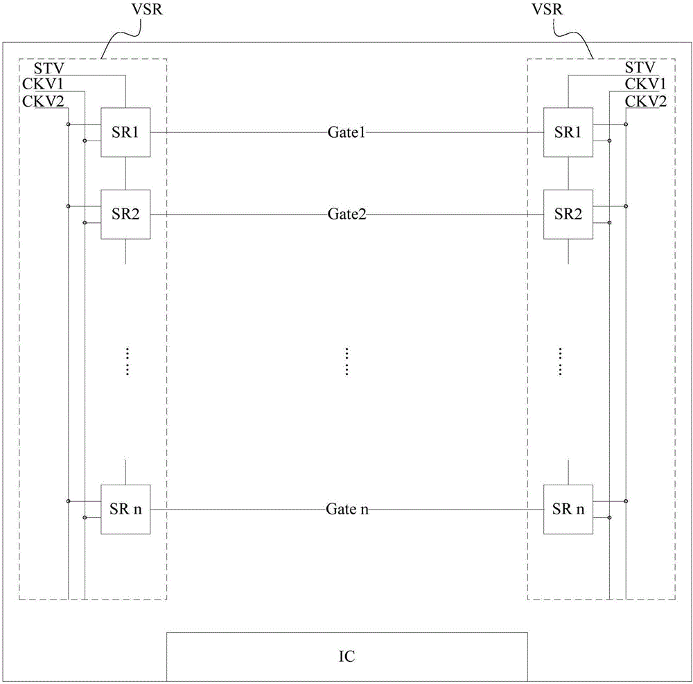
[0049] In this embodiment, the gate drive circuit adopts a double-sided driving method, that is, shift registers are arranged at both ends of each gate line, so that each shift register includes left and right sides respectively arranged at both ends of the same gate line shift register and right shift register.

[0050] The grouping situation and driving method of the shift registers in this embodiment are similar to the first embodiment, the difference is that: when each group of shift registers works, the left shift register and the right shift register connected to the same gate line The bit registers work concurrently, so the repetition is omitted here.

Embodiment 3

[0052] In this embodiment, the gate driving circuit adopts a double-sided driving manner, that is, a shift register is provided at both ends of each gate line.

[0053] Specifically, the shift registers can be divided into N groups, and each shift register in each group of shift registers is respectively connected to gate lines at an interval of N-1 rows; N is an integer greater than 1; each of the shift registers in each group The shift register includes a left shift register SL and a right shift register SR respectively arranged at two ends of the same gate line, that is, each shift register in each group of shift registers is alternately arranged. For example Figure 8 As shown, when N is 2, the shift register is divided into 2 groups. The left shift registers SL1, SL3 ... and the right shift registers SR1, SR3 ... contained in each shift register in the first group of shift registers are respectively connected to the gate lines Gate1, Gate3 ... of odd rows, the first The...


PUM


Abstract

The invention discloses a display panel driving method and a display panel. The method comprises the following steps: grouping shifting registers in a grid driving circuit, setting different frame starting signal terminals and different clock control signal terminals for the groups of shifting registers so as to control the working states of the groups of shifting registers at different frame display times; at first display frequency, controlling all of the groups of shifting registers to work for one time according to the sequence of the groups of shifting registers within each frame of scanning time to display an image, and inputting column overturning display signals with lower power consumption to data lines at this time to realize a point overturning display effect; and at second display frequency subjected to frequency reduction compared with the first display frequency, scanning all grid lines for one time within multiple frames of continuous scanning times according to the frequency reduction fold and the number of the groups of shifting registers so as to display an image. The number of display signals located by the data lines within each frame of scanning time is reduced, the times of negative and positive polarity switch of the display signals are reduced, and the power consumption is reduced.

Description

technical field [0001] The invention relates to the field of display technology, in particular to a method for driving a display panel and the display panel. Background technique [0002] At present, the bilateral driving method can be used in the display panel, such as figure 1 As shown, the gate drive circuit VSR is respectively arranged on the left and right sides of the display panel, as shown in figure 1 As shown, each VSR contains a plurality of cascaded shift registers SR1, SR2...SRn, and the output terminals of each shift register are connected to Gate1, Gate2...Gate n in one-to-one correspondence with the gate lines in the display panel, two groups The first-stage shift register SR1 of the VSR is respectively connected to the same frame start signal terminal STV, and the shift registers SR1, SR2...SRn of the two groups of VSRs are connected to the clock control signal terminals CKV1 and CKV2. Under the control of the frame start signal terminal STV and the clock c...

Claims


Application Information

Patent Timeline
Patent Type & Authority Applications(China)
IPC IPC(8): G09G3/20
CPCG09G3/20G09G2310/0267G09G2310/0286
Inventor 陈晓梦黄敏吴常志杨康鹏许育民
Owner XIAMEN TIANMA MICRO ELECTRONICS
Why Eureka
Try Eureka