Surge protection circuit

A surge protection and protection circuit technology, applied in emergency protection circuit devices, circuit devices, emergency protection circuit devices for limiting overcurrent/overvoltage, etc. device malfunction and other problems, to ensure the performance of environmental adaptability, optimize the cost of the whole machine, and improve the reliability of performance

Inactive Publication Date: 2017-05-10
BESTBRIGHT ELECTRONICS
View PDF8 Cites 2 Cited by
  • Summary
  • Abstract
  • Description
  • Claims
  • Application Information

AI Technical Summary

Problems solved by technology

[0002] At present, the power input part of high-reliability electronic products usually uses clamp-type and switch-type products in series for surge protection; in the actual product design process, due to the working mode and electrical parameters of clamp-type and switch-type protection devices And characteristics (such as: breakdown voltage, response time, static impedance, dynamic impedance, etc.) are quite different. For example, the voltage of the clamping type and the switching type protection device are directly connected in series, and the voltage division of the protection device is not balanced. When the machine product is working normally, it will accelerate the aging of the protection device and seriously affect the performance and reliability of the whole machine product. Therefore, the product voltage of the clamp type and switch type protection device cannot be directly selected in series; in order to improve the reliability of the whole machine product In the existing traditional scheme design, the breakdown voltage of the clamp type and switch type protection products usually meet the power input requirements respectively. The series breakdown voltage of this traditional scheme is basically more than twice the input voltage, which cannot effectively guarantee the power supply. The residual voltage under the surge impact puts a lot of pressure on the subsequent stage circuit, making the layout difficult and the cost of the whole machine high

Method used


Image

  • Surge protection circuit
  • Surge protection circuit
  • Surge protection circuit

Examples


Embodiment 1

[0030] Comparison of surge protection schemes for ungrounded power supply or DC power supply of the whole machine: (this scheme can also be used as the second level of surge protection to reduce residual voltage)

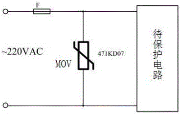
[0031] Such as figure 2 Shown is the traditional surge protection scheme, using varistors for differential surge protection;

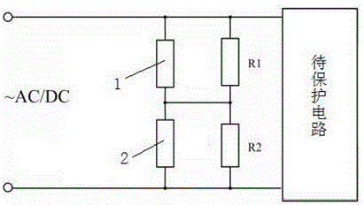
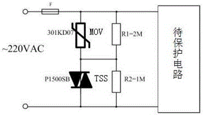
[0032] Such as image 3 It is shown that the surge protection circuit described in Embodiment 1 of the present invention uses the resistance ratio of the peripheral circuit, and adopts the method of connecting the piezoresistor TSS and the semiconductor discharge tube MOV in series to make a differential surge protection circuit; image 3 The protection circuit shown uses the resistance ratio of the voltage dividing matching circuit to distribute the voltage at both ends of the protection device fixedly. Under the normal operation of the circuit, the voltage at both ends of the varistor TSS is 2 / 3 times of the input voltage Vin of the power...

Embodiment 2

[0035] Comparison of surge protection schemes for whole machine grounding power supply:

[0036] Such as Figure 6 : The traditional surge protection scheme uses varistors for differential protection, and uses varistors and gas discharge tubes in series for common mode protection. Due to the large difference in dynamic parameters between varistors and discharge tubes, the varistor and gas discharge The tube selects the voltage model according to the input power Vin;

[0037] Such as Figure 7 Shown is the surge protection circuit described in Embodiment 2 of the present invention, using a voltage division matching circuit to fix the voltage across the varistor MOV and the ceramic gas discharge tube GDT according to the resistance ratio of the resistors; image 3 The resistance matching is designed in the middle. Under normal power supply conditions, the voltage at both ends of the varistor MOV is 2 / 3 times of the input power Vin, and the voltage at both ends of the ceramic g...

Embodiment example 3

[0040] The case grounding of the whole machine has withstand voltage requirements Comparison of surge protection schemes for power supply products

[0041] Such as Figure 10 Shown is the traditional surge protection scheme, using varistors for differential protection, and using varistors and discharge tubes in series for common mode protection. Due to the HI-pot withstand voltage requirements, the breakdown voltage of discharge tube products is required to be Greater than 1500Vac;

[0042] Such as Figure 11Shown is the surge protection circuit described in Embodiment 3 of the present invention, using the impedance distribution of the voltage division matching circuit to fix the voltage at both ends of the protection device; as shown in the scheme above, under normal 220Vac power supply, the voltage at both ends of the varistor MOV It is 2 / 5 times of the power input vin, and the voltage across the ceramic gas discharge tube GDT is 3 / 5 times of the power input; when making 1...


PUM


Abstract

The invention discloses a surge protection circuit, and relates to the technical field of an emergency protection circuit device used for limiting overvoltage while a circuit is not cut off. The surge protection circuit comprises a surge suppression circuit and a voltage sharing matching circuit, wherein the surge suppression circuit comprises a clamping type surge protector and a switch type surge protection device, one end of the clamping type surge protector is a wiring end of the protection circuit, the other end of the clamping type surge protection device is connected with one end of the switch type surge protection device, the other end of the switch type surge protection device is the other wiring end of the protection circuit, the voltage sharing matching circuit comprises voltage sharing matching resistors R1 and R2, the resistor R1 is connected in parallel with the clamping type surge protection device, and the resistor R2 is connected in parallel with the switch type surge protection device. By the circuit, the residual voltage during surge impact of the whole machine is reduced, the environmental adaptability of the circuit is effectively ensured, and the cost of the whole machine is optimized.

Description

technical field [0001] The invention relates to the technical field of emergency protection circuit devices for limiting overvoltage without cutting off circuits, in particular to a surge protection circuit with good protection effect. Background technique [0002] At present, the power input part of high-reliability electronic products usually uses clamp-type and switch-type products in series for surge protection; in the actual product design process, due to the working mode and electrical parameters of clamp-type and switch-type protection devices And characteristics (such as: breakdown voltage, response time, static impedance, dynamic impedance, etc.) are quite different. For example, the voltage of the clamping type and the switching type protection device are directly connected in series, and the voltage division of the protection device is not balanced. When the machine product is working normally, it will accelerate the aging of the protection device and seriously af...

Claims


Application Information

Patent Timeline
Patent Type & Authority Applications(China)
IPC IPC(8): H02H9/04
CPCH02H9/04
Inventor 张明志周云福
Owner BESTBRIGHT ELECTRONICS
Why Eureka
Try Eureka