Full-digital phase-locked loop-based resonant current phase controller and method

An all-digital phase-locked loop and phase controller technology, applied to the phase angle between voltage and current, irreversible DC power input to AC power output, instruments, etc., can solve the problem that it is difficult to ensure the accuracy of phase control , It is difficult to construct the transfer function of the phase controller and other issues, so as to achieve the effect of stable and reliable operation process and good phase control accuracy

Inactive Publication Date: 2017-05-10
ELECTRIC POWER RES INST OF GUANGDONG POWER GRID
View PDF2 Cites 15 Cited by
  • Summary
  • Abstract
  • Description
  • Claims
  • Application Information

AI Technical Summary

Problems solved by technology

[0004] The analog method based on discrete devices is difficult to guarantee the accuracy of phase control when the frequency of the controlled signal is high; the phase controller parameters of the digital method based on digital chips are very sensitive to the resonant load parameters. Varying applications, it is difficult to construct a phase controller transfer function applicable to the whole range

Method used


Image

  • Full-digital phase-locked loop-based resonant current phase controller and method
  • Full-digital phase-locked loop-based resonant current phase controller and method
  • Full-digital phase-locked loop-based resonant current phase controller and method

Examples


Embodiment 1

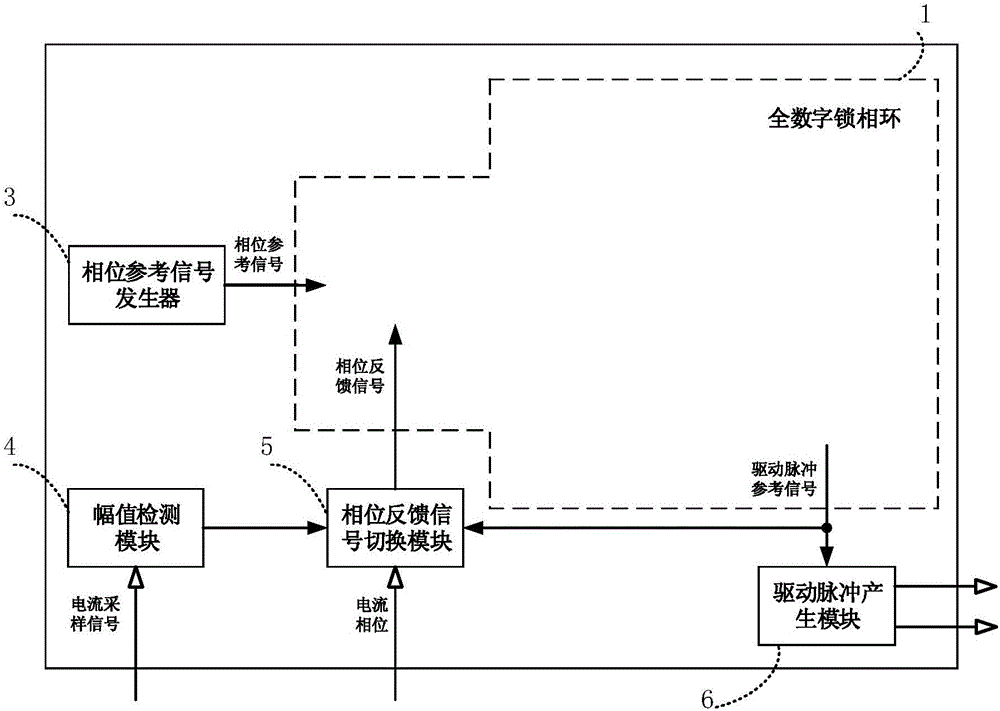
[0074] Embodiments of the present invention provide a resonant current phase controller based on an all-digital phase-locked loop, such as figure 1 As shown, it includes an all-digital phase-locked loop 1, a phase reference signal generator 3, an amplitude detection module 4, a phase feedback signal switching module 5 and a driving pulse generation module 6;

[0075] The output end of the phase reference signal generator 3 is connected to the all-digital phase-locked loop 1;

[0076] The all-digital phase-locked loop 1 is connected with the phase feedback signal switching module 5 to form a circuit loop;

[0077] The input end of the phase feedback signal switching module 5 is connected to the amplitude detection module 4;

[0078] The driving pulse generating module 6 is connected to the output end of the all-digital phase-locked loop 1 .

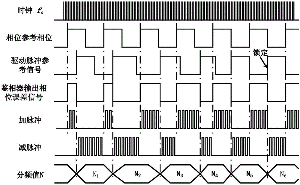
[0079] see figure 2 , the all-digital phase-locked loop 1 detects the phase difference between the phase reference signal output by t...

Embodiment 2

[0089] An embodiment of the present invention is based on a resonant current phase controller of an all-digital phase-locked loop, such as Figure 4 As shown, it includes a communication module 2, an all-digital phase-locked loop 1, a phase reference signal generator 3, an amplitude detection module 4, a phase feedback signal switching module 5 and a driving pulse generation module 6;

[0090] The communication module 2 is respectively connected to the phase reference signal generator 3 and the all-digital phase-locked loop 1;

[0091] The output end of the phase reference signal generator 3 is connected to the all-digital phase-locked loop 1;

[0092] The all-digital phase-locked loop 1 is connected with the phase feedback signal switching module 5 to form a circuit loop;

[0093] The input end of the phase feedback signal switching module 5 is connected to the amplitude detection module 4;

[0094] The driving pulse generating module 6 is connected to the output end of the...

Embodiment 3

[0097] An embodiment of the present invention is based on a resonant current phase controller of an all-digital phase-locked loop, such as Figure 5 As shown, it includes a communication module 2, an all-digital phase-locked loop 1, a phase reference signal generator 3, an amplitude detection module 4, a phase feedback signal switching module 5 and a driving pulse generation module 6;

[0098] The communication module 2 is respectively connected to the phase reference signal generator 3 and the all-digital phase-locked loop 1;

[0099] The output end of the phase reference signal generator 3 is connected to the all-digital phase-locked loop 1;

[0100] The all-digital phase-locked loop 1 is connected with the phase feedback signal switching module 5 to form a circuit loop;

[0101] The input end of the phase feedback signal switching module 5 is connected to the amplitude detection module 4;

[0102] The driving pulse generating module 6 is connected to the output end of the...


PUM


Abstract

The embodiment of the invention discloses a full-digital phase-locked loop-based resonant current phase controller and a method thereof, wherein the phase of a resonant current in an application scenario wherein medium-high-frequency and load parameters are changing within a large range can be controlled. According to the embodiments of the invention, the full-digital phase-locked loop-based resonant current phase controller comprises a full-digital phase-locked loop, a communication module, a phase reference signal generator, a phase feedback signal switching module, an amplitude detection module and a driving signal generation module. According to the invention, according to the phase difference between a phase reference signal and a phase feedback signal, the frequency and the phase of a drive pulse reference signal can be adjusted quickly. Therefore, the phase reference signal of the resonance current phase can be automatically tracked and controlled. The problems in the prior art that the traditional method is poor in control accuracy and complicated in parameter design of a control loop system can be avoided. Moreover, according to the technical scheme of the invention, the implementation scheme is simple and the parameter design is flexible. The requirements of medium-high-frequency multi-phase resonant currents, such as digitized phase or phase difference, accurate closed loop control and the like, can be met.

Description

technical field [0001] The invention relates to the field of phase-locked loop digital circuits, in particular to a resonant current phase controller and method based on an all-digital phase-locked loop. Background technique [0002] At present, power systems containing multi-phase series resonant inverters are widely used in high-frequency AC distributed power supply systems, rotating magnetic field generators, and partitioned induction heating. The control of phase or phase difference of high-frequency AC sinusoidal current or voltage puts forward higher requirements. Currently, there are not many relevant studies on the phase control of such AC voltage or current signals. [0003] Traditional methods mainly include analog methods based on discrete devices and digital methods based on digital chips. The former generally uses a circuit composed of an analog multiplier and a low-pass filter to detect the phase difference between the controlled signal and the reference signa...

Claims


Application Information

Patent Timeline
Patent Type & Authority Applications(China)
IPC IPC(8): H02M7/48G01R25/00
CPCG01R25/00H02M7/48H02M1/0012H02M7/4815Y02B70/10
Inventor 易斌林国营宋强潘峰赵伟
Owner ELECTRIC POWER RES INST OF GUANGDONG POWER GRID
Why Eureka
Try Eureka