
Segmented resistance type IGBT driving circuit and control method thereof

A segmented resistance and drive circuit technology, applied in the control of segmented resistive IGBT drive circuits, in the field of segmented resistive IGBT drive circuits, can solve the problems of low application frequency and large switching losses of IGBT tubes, and improve device application frequency, reduced switching loss, and easy programming

Inactive Publication Date: 2017-05-10
NANJING NARI GROUP CORP
View PDF5 Cites 11 Cited by
  • Summary
  • Abstract
  • Description
  • Claims
  • Application Information

AI Technical Summary

Problems solved by technology

[0004] The purpose of the present invention is to overcome the deficiencies in the prior art, provide a segmented resistance type IGBT drive circuit, and solve the technical problems of large switching losses and low application frequency of IGBT tubes in the prior art

Method used


Image

  • Segmented resistance type IGBT driving circuit and control method thereof
  • Segmented resistance type IGBT driving circuit and control method thereof
  • Segmented resistance type IGBT driving circuit and control method thereof

Examples


Embodiment Construction

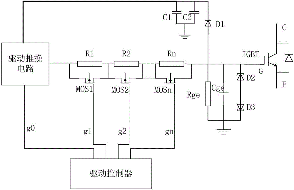
[0023] On the basis of the traditional drive technology, the present invention proposes a segmented resistance type IGBT drive circuit and a control method, which controls the drive resistance of the IGBT at the rising and falling edges of the gate drive pulse, reduces the switching loss of the IGBT device, and improves The application frequency of the device. The present invention will be further described below in conjunction with the accompanying drawings. The following examples are only used to illustrate the technical solution of the present invention more clearly, but not to limit the protection scope of the present invention.

[0024] Such as figure 1 As shown, IGBT is the driven element, G is the gate of IGBT, C is the collector, and E is the emitter. The segmented resistance type IGBT driving circuit provided by the present invention includes a driving push-pull circuit, a segmented resistance driving circuit and an IGBT gate clamping circuit.

[0025] The segmente...


PUM


Abstract

The invention discloses a segmented resistance type IGBT driving circuit, which is characterized in that a segmented resistor driving circuit comprises a plurality of segmented resistors which are connected in series, both ends of each segmented resistors are connected with a bypass MOS transistor in parallel; each bypass MOS transistor and a driving push-pull circuit are connected with a driving controller; and an IGBT gate clamping circuit comprises an IGBT gate voltage-stabilized clamping circuit and an IGBT gate power supply clamping circuit. The invention further discloses a control method of the segmented resistance type IGBT driving circuit, which is characterized in that a pulse rising edge and a falling edge are driven at the gate, and the size of the gate driving resistance is changed through switching of the bypass MOS transistors. The segmented resistance type IGBT driving circuit and the control method thereof can achieve the purposes of reducing the switching loss of an IGBT device and improving the application frequency of the device while ensuring suppression for surge and gate oscillation.

Description

technical field [0001] The invention relates to a segmented resistance type IGBT drive circuit and a control method for the segmented resistance type IGBT drive circuit, belonging to the technical field of power electronics. Background technique [0002] Like other power electronic devices, the reliability of IGBT depends on the driving circuit. The high input impedance of IGBT makes it easier to drive, but it is also easy to cause excessive source current or excessive dv / dt, resulting in latch-up effect and failure. Therefore, a drive circuit with excellent performance is a necessary condition to ensure the efficient and reliable operation of the IGBT. The gate drive resistance Rg of the IGBT has a direct impact on the driving effect, and the turn-on and turn-off of the IGBT depends on the size of Rg. The larger Rg is, the longer its turn-on and turn-off time is, and the switching loss is also larger, but the surge voltage becomes smaller, which reduces the possibility of ...

Claims


Application Information

Patent Timeline
IPC IPC(8): H03K17/567H03K17/081
CPCH03K17/567H03K17/08116H03K2217/0036
Inventor 郑玉平李伟邦侯凯何安然蒋应伟范镇淇王后生王志刚
Owner NANJING NARI GROUP CORP
Learn More