Vital signs monitoring via radio reflections

A technology for signal reflection and signal transmission, applied in the field of this application

Active Publication Date: 2017-05-10
MASSACHUSETTS INST OF TECH
View PDF7 Cites 9 Cited by
  • Summary
  • Abstract
  • Description
  • Claims
  • Application Information

AI Technical Summary

Problems solved by technology

As a result, experimental setups for past methods often required a single person lying still near the device

Method used


Image

  • Vital signs monitoring via radio reflections
  • Vital signs monitoring via radio reflections
  • Vital signs monitoring via radio reflections

Examples


Embodiment Construction

[0052] 1 System overview

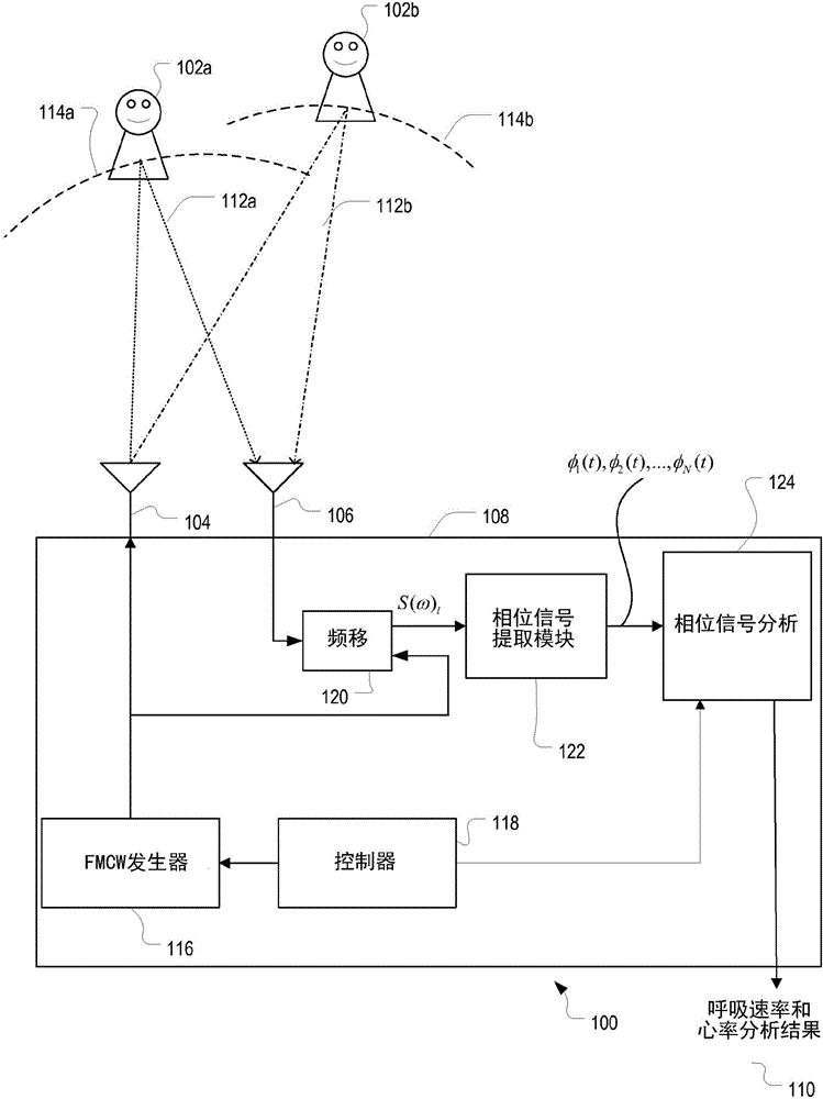
[0053] see figure 1 , the vital signs monitoring system 100 monitors the vital signs (eg, breathing rate and heart rate) of the one or more subjects 102a, 102b without requiring any physical contact between the one or more subjects and the vital signs monitoring system 100 touch. Vital signs monitoring system 100 includes transmit antenna 104 , receive antenna 106 and signal processing subsystem 108 . It should be noted that in some examples, system 100 includes multiple receive antennas and / or multiple transmit antennas, rather than having a single receive antenna and a single transmit antenna. However, to simplify the description of the vital sign monitoring system, the following description only refers to the single receive antenna / single transmit antenna embodiment.

[0054] In general, vital signs monitoring system 100 transmits low power wireless signals from transmit antenna 104 into the environment surrounding system 100 . The transmitt...


PUM


Abstract

A method for monitoring periodic motions of one or more subjects uses signal reflections from the subjects. The method includes emitting a transmitted signal from a transmitting antenna and receiving a received signal at one or more receiving antennas. The received signal includes a combination of a number of reflections of the transmitted signal, at least some of which are associated with the subjects. The received signal, including the reflections, is processed to determine an estimate of a fundamental frequency of the periodic motions.

Description

[0001] Cross References to Related Applications [0002] This application claims U.S. Provisional Application No. 61 / 985,066, filed April 28, 2014, entitled "MULTI-PERSON MOTION TRACKING VIABODY RADIO REFLECTIONS," and filed February 17, 2015 Priority to US Provisional Application No. 62 / 117,087, filed entitled "VITAL SIGNS MONITORING VIA RADIOREFLECTIONS (Vital Signs Monitoring by Radio Reflection)." [0003] This application is related to U.S. Provisional Application No. 61 / 888,662, filed October 9, 2013, entitled "MOTION TRACKING VIA BODY RADIOREFLECTIONS," filed February 24, 2014, entitled U.S. Provisional Application No. 61 / 943,957 for "MULTI-PERSON MOTION TRACKING VIA BODY RADIO REFLECTIONS (MULTI-PERSON MOTION TRACKING VIA BODY RADIO REFLECTIONS)" and filed October 9, 2014 entitled "MOTION TRACKING VIA BODY RADIO REFLECTIONS ( Motion Tracking by Radio Reflections from the Body)" U.S. Invention Application No. 14 / 510,263, without claiming priority from the aforementioned ...

Claims


Application Information

Patent Timeline
Patent Type & Authority Applications(China)
IPC IPC(8): A61B5/08
CPCA61B5/08A61B5/113G01S7/415G01S13/522G01S13/536A61B5/0255
Inventor 法德尔·阿迪布扎卡里·爱德华·卡贝莱克迪纳·卡塔比
Owner MASSACHUSETTS INST OF TECH
Why Eureka
Try Eureka