Electrolysis device
A technology of electrolysis device and electrolysis unit, which is applied in electrolysis components, electrolysis process, water treatment parameter control and other directions, can solve the problems of slow electrolyte flow rate, fast electrolyte flow rate, time deviation, etc., to promote electrode reaction and improve production The effect of efficiency
- Summary
- Abstract
- Description
- Claims
- Application Information
AI Technical Summary
Problems solved by technology
Method used
Image

Examples
no. 1 Embodiment approach
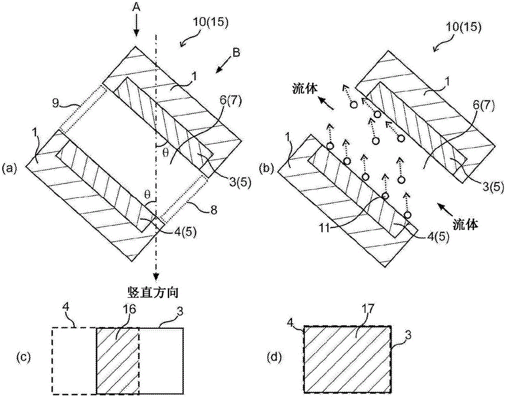
[0116] figure 1 (a) and (b) are schematic cross-sectional views of the electrolysis device of the first embodiment, respectively, figure 1 The (c) is used to explain that viewed from the vertical direction A figure 1 The superimposed figure of the upper electrode and the lower electrode in the case of the electrolysis device shown in (a), figure 1 The (d) is used to explain that viewed from the direction B perpendicular to the main surface of the lower electrode figure 1 (a) is a diagram showing superimposition of the upper electrode and the lower electrode in the case of the electrolysis device.
[0117] The electrolysis device 15 of the first embodiment is characterized in that it includes an electrolysis unit 10. The electrolysis unit 10 includes a fluid flow path 7 to be treated, at least one pair of electrodes 5 for electrolysis, an inlet 8 and an outlet 9, and the pair of electrodes 5 for electrolysis. It is arranged in an inclined manner relative to the vertical...
no. 2 Embodiment approach
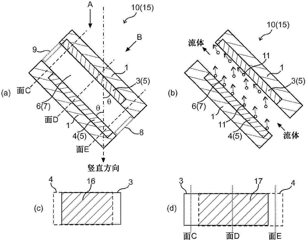
[0145] figure 2 (a) and (b) are schematic cross-sectional views of the electrolysis device of the second embodiment, respectively, figure 2 The (c) is used to explain that viewed from the vertical direction A figure 2 (a) The superposition diagram of the upper electrode and the lower electrode when the electrolysis device is shown, figure 2 The (d) is used to explain that viewed from the direction B perpendicular to the main surface of the lower electrode figure 2 (a) A superposition diagram of the upper electrode and the lower electrode in the case of the electrolysis device shown in (a).
[0146] exist figure 1 In the shown electrolysis device, the upper electrode 3 and the lower electrode 4 are arranged so that when viewed from the direction B, the upper electrode 3 and the lower electrode 4 overlap substantially on the entire surface, but in the electrolysis device 15 of the second embodiment, Both are arranged so that the upper electrode 3 is located at a higher...
no. 3 Embodiment approach
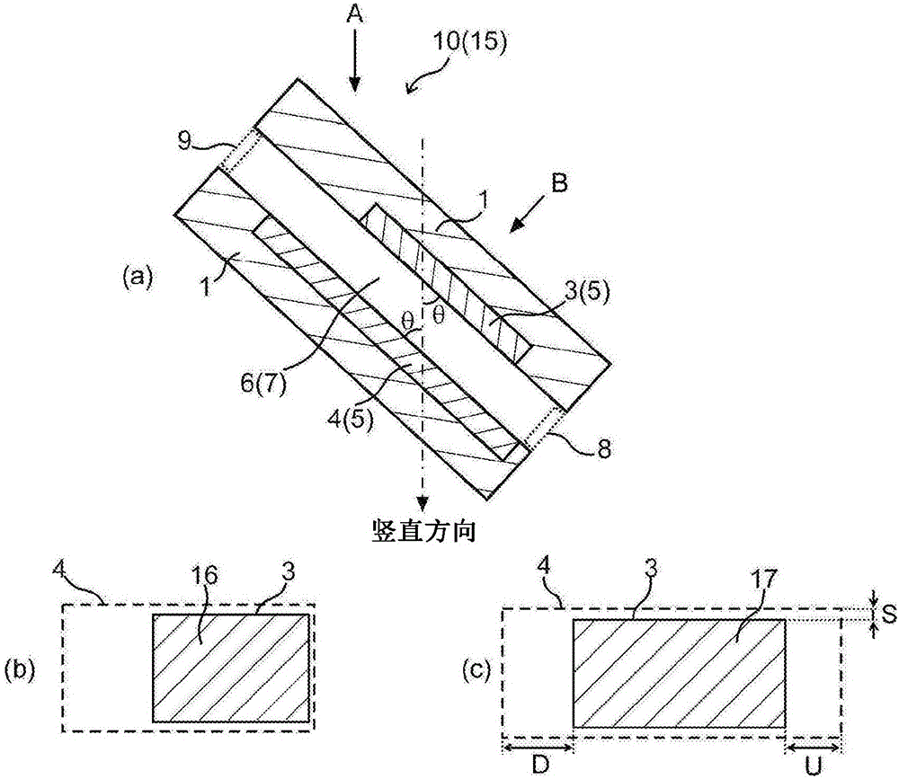
[0152] image 3 (a) is a schematic cross-sectional view of the electrolysis device of the third embodiment, image 3 The (b) is used to illustrate that viewed from the vertical direction A image 3 The superimposed diagram of the upper electrode and the lower electrode in the electrolysis device shown in (a), image 3 The (c) is used to illustrate the observation from the direction B perpendicular to the electrode surface of the lower electrode image 3 (a) is a diagram showing overlapping of the upper electrode and the lower electrode in the electrolysis device.
[0153] exist figure 1 , 2 In the shown electrolysis device 15, the electrode surface of the upper electrode 3 and the electrode surface of the lower electrode 4 have substantially the same size, but in the electrolysis device 15 of the third embodiment, the electrode surface of the lower electrode 4 is larger than the electrode surface of the upper electrode 3. The electrode surface is large. Additionally, if...
PUM
 Abstract
Description
Claims
Application Information
 - R&D
- Intellectual Property
- Life Sciences
- Materials
- Tech Scout
- Unparalleled Data Quality
- Higher Quality Content
- 60% Fewer Hallucinations
Browse by: Latest US Patents, China's latest patents, Technical Efficacy Thesaurus, Application Domain, Technology Topic, Popular Technical Reports.
© 2025 PatSnap. All rights reserved.Legal|Privacy policy|Modern Slavery Act Transparency Statement|Sitemap|About US| Contact US: help@patsnap.com