Turbomachines including means for decoupling fans

A technology of coupling device and turbine, which is applied to the components of pumping device for elastic fluid, pump device, safety device, etc., can solve the problems of increasing the aerodynamic resistance of the engine, the inability of the fan to rotate, and the inability of the aircraft to drive.

Active Publication Date: 2018-11-13
SAFRAN AIRCRAFT ENGINES SAS
View PDF7 Cites 0 Cited by
  • Summary
  • Abstract
  • Description
  • Claims
  • Application Information

AI Technical Summary

Problems solved by technology

[0008] In fact, in the event of loss of blades, this torsional moment also risks seriously damaging the reduction device, which could then become blocked and prevent the fan from rotating
This would have the result of suddenly increasing the aerodynamic drag of the engines, making the aircraft undrivable

Method used


Image

  • Turbomachines including means for decoupling fans
  • Turbomachines including means for decoupling fans
  • Turbomachines including means for decoupling fans

Examples


Embodiment Construction

[0029] In the following description, the same reference numerals designate the same components or have similar functions.

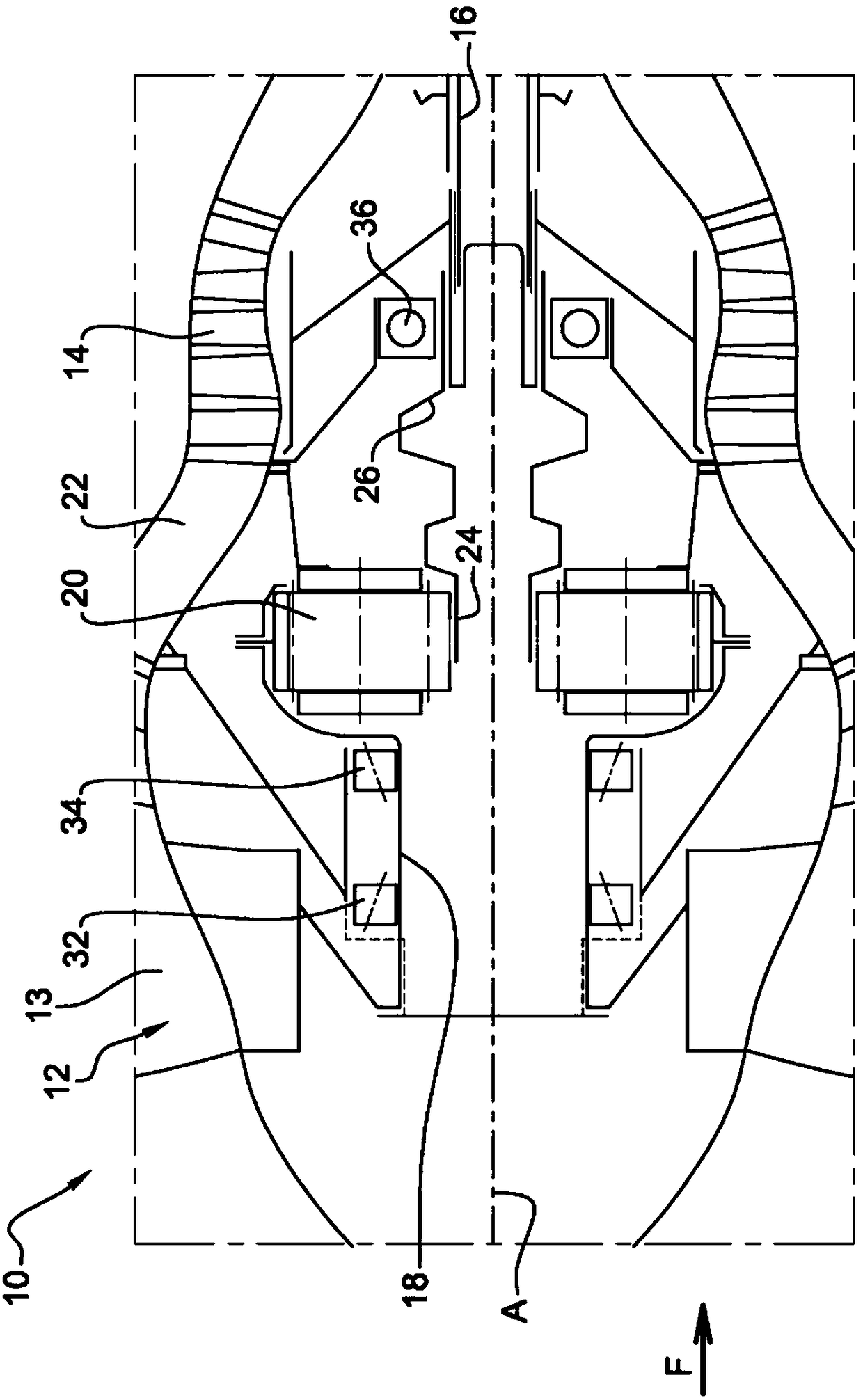
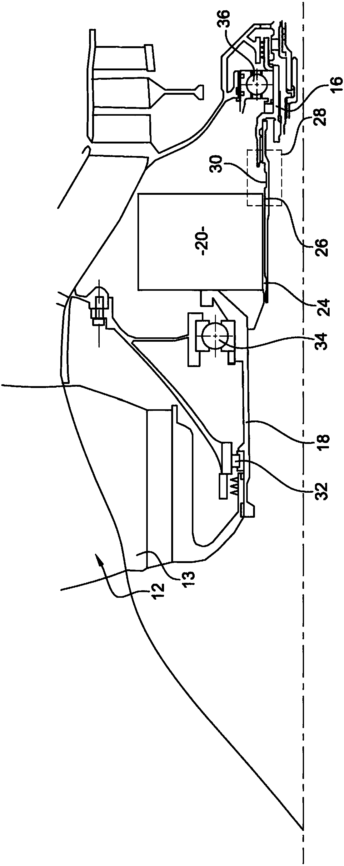
[0030] exist figure 1 A turbine, such as a turbine engine 10, made according to the state of the art is shown in . In known manner, the turbine engine 10 includes, from upstream to downstream along airflow flow "F", a fan 12 , a low pressure compressor 14 , a high pressure compressor, a combustor, a high pressure turbine and a low pressure turbine (not shown). The fan 12 includes blades 13 . The high-pressure compressor and the high-pressure turbine are connected by a high-pressure shaft and together with the high-pressure shaft form a high-pressure body. The low-pressure compressor 14 and the low-pressure turbine are connected via a low-pressure shaft 16 and together form a low-pressure body. As regards the fan 12 , it is supported by a fan shaft 18 which, in the example shown, is rotationally coupled to the BP shaft 16 by means of a device 20 for red...


PUM


Abstract

The invention relates to a turbomachine comprising a fan shaft (12) driven by a turboshaft (16) via a device (20) for reducing the rotational speed, characterized in that the turbomachine comprises a Decoupling means (28) between the device (20) and the turbine shaft (16) capable of decelerating in response to exceeding a determined resistive torque applied to the turbine shaft (16) by the deceleration device (20) The device (20) and the turbine shaft (16) are decoupled.

Description

technical field [0001] The field of the invention is that of aeronautical turbines, more particularly of twin-flow turbines including a reduction device for driving a fan. Background technique [0002] Traditionally, a turbomachine comprises, starting upstream, one or several compressor modules positioned in series, which compress the air drawn into the air intake. The air is then introduced into a combustion chamber where it mixes with fuel and burns. The combustion gases pass through one or several turbine modules driving a compressor through an associated turbine shaft. The gas is finally injected into nozzles to generate propulsion, or onto a free turbine to generate power captured on the drive shaft. [0003] Current dual-flow turbines with strong dilution ratios comprise several compressor stages through which the main flow passes, including inter alia a low-pressure (BP) compressor and a high-pressure (HP) compressor. These low pressure (BP) compressors and high pr...

Claims


Application Information

Patent Timeline
Patent Type & Authority Patents(China)
IPC IPC(8): F01D21/04F02K3/06F02C3/113F02C7/36
CPCF01D21/045F02C3/113F02C7/36F02K3/06F05D2260/4031F05D2260/40311Y02T50/60F01D5/02F01D15/12F01D21/003F01D21/06F04D25/045F04D29/054F04D29/325F04D29/388F05D2220/32F05D2240/60F05D2260/311
Inventor 亚历山大·谭-金朱利安·法比恩·帕特里克·比库利特
Owner SAFRAN AIRCRAFT ENGINES SAS
Why Eureka
Try Eureka