Monitoring systems for gas engines

A gas engine and monitoring system technology, applied in the direction of engine components, engine control, combustion engine, etc., can solve problems such as long flushing time, achieve short flushing time and improve safety

Active Publication Date: 2019-05-14
WARTSILA FINLAND OY
View PDF8 Cites 0 Cited by
  • Summary
  • Abstract
  • Description
  • Claims
  • Application Information

AI Technical Summary

Problems solved by technology

Because this type of gas engine is usually used as backup power, a relatively fast response to power demand is required, and the longer flush time is a disadvantage

Method used


Image

  • Monitoring systems for gas engines
  • Monitoring systems for gas engines

Examples


Embodiment Construction

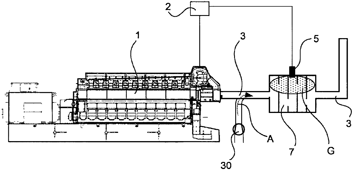
[0017] exist figure 1 , it shows an engine 1 apparatus including a monitoring system 2 for a gas engine 1, a reciprocating internal combustion engine 1 using gas as fuel, connected to a Outlet channel 3 of the outlet channel 3 is arranged with a fan 30 associated with the outlet channel 3 for use when the engine 1 is not started (in other words, when the engine has not started operation based on the combustion of fuel) and in the outlet channel 3 Air A is used to flush the outlet channel 3 where unburned fuel gas G may accumulate. At least one NOx sensor 5 is positioned in the outlet channel 3 at a location where unburned fuel gas G may accumulate. The location where the sensor 5 is positioned and where unburned fuel gas G may accumulate can be, for example, a muffler 7, such as figure 1 shown, but it could also be some kind of closed curved top of the boiler, catalytic converter, heat recovery system, outlet channel or corresponding position.

[0018] The arrangement of th...


PUM


Abstract

A monitoring system (2) for a gas engine (1), the engine (1) is a reciprocating internal combustion engine using gas as fuel, the engine (1) is connected to an outlet channel (3) for conducting the exhaust gases out of the engine (1), there is a fan (30) arranged in connection with the outlet channel (3) for flushing the outlet channel (3) with air (A) in case of non-started engine (1) and when there may be unburned fuel gas (G) accumulated in the outlet channel (3). In the system there is at least one NOx-sensor (5) located in the outlet channel (3) in a location where unburned fuel gas (G) may accumulate.

Description

technical field [0001] The invention relates to a monitoring system for a gas engine, said engine being a reciprocating internal combustion engine using gas as fuel, the engine being connected to an outlet channel for leading exhaust gases out of the engine, arranged in relation to said outlet channel A fan for flushing the outlet passage with air when the engine is not started and when unburned fuel gas accumulates in the outlet passage. Background technique [0002] Reciprocating gas internal combustion engines typically use methane or other lighter-than-air gases as fuel. During start-up, gaseous fuel is supplied to the cylinders. Under normal conditions, fuel is supplied to the cylinder, compressed, then the gas / air mixture is ignited or ignited, and after combustion, the combusted exhaust is expelled from the cylinder during the exhaust stroke. If ignition does not occur for some reason, unburned fuel gases are expelled into the exhaust system, ie, the outlet passage,...

Claims


Application Information

Patent Timeline
Patent Type & Authority Patents(China)
IPC IPC(8): F01N3/32F01N11/00F01N1/14F02D35/00
CPCF01N1/14F01N3/32F01N11/00F01N11/007F01N2270/08F01N2270/10F01N2550/14F01N2560/025F01N2560/026F01N2590/10F01N2900/08F02D35/0038Y02T10/12Y02T10/40
Inventor J·托尔库拉M·勒夫霍姆J·科特莱宁
Owner WARTSILA FINLAND OY
Why Eureka
Try Eureka