Metal gasket

A technology of metal gaskets and metal plates, applied in the direction of engine seals, mechanical equipment, engine components, etc., can solve the problem of being unable to cope with the narrowing of the width of the sealing surface

Active Publication Date: 2019-02-12
NOK CORP
View PDF11 Cites 0 Cited by
  • Summary
  • Abstract
  • Description
  • Claims
  • Application Information

AI Technical Summary

Problems solved by technology

However, the maximum width W of the sealing rib 52 1 The relationship with the size (diameter d) of the bolt hole 51 is d1 , so it cannot cope with the narrowing of the sealing surface width

Method used


Image

  • Metal gasket
  • Metal gasket
  • Metal gasket

Examples


Embodiment

[0079] Next, embodiments of the present invention will be described with reference to the accompanying drawings.

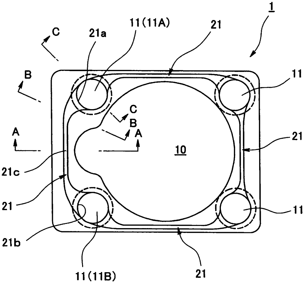
[0080] figure 1 as well as figure 2 Indicates the metal spacer in the embodiment of the present invention. The metal gasket 1 in this embodiment is a flat metal gasket mounted on a flange portion of an engine or auxiliary machine, EV (electric vehicle), HEV (hybrid electric vehicle) inverter, etc. in vehicles such as automobiles, It has a prescribed plane layout (rectangular plane in the figure), and on this plane, there are holes 10 and a plurality of bolt holes 11 (four places in the figure), and the internal pressure and outside water (external foreign matter) should be sealed at the same time. The sealing rib 21.

[0081] Such as figure 1 As shown, a plurality of bolt holes 11 are arranged on the flat plate of the metal gasket 1 , and sealing protrusions 21 are arranged between the bolt holes 11 adjacent to each other. In the figure, there are four bol...


PUM


Abstract

The invention provides a metal gasket, which can improve the sealing performance through the sealing rib, and can meet the requirement of narrowing the width of the sealing surface. In order to achieve this purpose, a flat metal gasket with a plurality of bolt holes is provided, and a sealing rib is provided between the bolt holes adjacent to each other, and one end of the sealing rib is connected with the bolt hole on one side, and the other end is connected with the bolt hole on one side. Bolt hole connection on the other side. The sealing rib is made into a tapered shape in which the width is the narrowest at the central portion between the bolt holes, and the width gradually increases from the central portion between the bolt holes to the bolt hole. In addition, when the diameter of the head support surface of the fastening bolt inserted into the bolt hole is D, the diameter of the bolt hole is d, and the maximum width of the sealing rib is W1, the relationship of D>d≥W1 is satisfied. The metal gasket is a gasket made of a metal plate, or a gasket covered with a rubber-like elastic body on both sides or one side in the thickness direction of the metal plate.

Description

technical field [0001] The invention relates to a metal gasket related to sealing technology. The metal gasket of the present invention is used, for example, in the fields related to automobiles, or in other fields. Background technique [0002] In the conventional flat metal gasket, a sealing rib is formed on the flat surface, and the sealing rib is compressed when the bolt is connected to seal the internal pressure and the water on the outside. By forming the sealing convex strip, the sealing part is in line contact. In addition to increasing the pressure on the sealing surface, the sealing convex strip is also required in order to make the sealing part closely follow the flatness of the surface to be sealed. [0003] In recent years, due to the increase in fuel consumption of automobiles and other vehicles, the miniaturization and weight reduction of flanges used in inverters for engines and auxiliary equipment, EV (electric vehicles), and HEV (hybrid electric vehicles) ...

Claims


Application Information

Patent Timeline
Patent Type & Authority Patents(China)
IPC IPC(8): F16J15/08
CPCF16J15/0818F16J2015/085F16J2015/0856F16J2015/0862F16J15/10
Inventor 渡边健丹治功中冈真哉
Owner NOK CORP
Why Eureka
Try Eureka