Ion source

A technology of ion source and plasma, applied in the field of ion source with gas injection part on the magnetic pole, which can solve the problems of high production cost and complex structure

Active Publication Date: 2017-05-10
发仁首路先株式会社
View PDF8 Cites 2 Cited by
  • Summary
  • Abstract
  • Description
  • Claims
  • Application Information

AI Technical Summary

Problems solved by technology

Therefore, the traditional solution is not only complicated in structure but also high in production cost.
Moreover, the method of removing the ions sputtered on the electrodes or magnetic poles by switching the polarity is relatively limited.

Method used


Image

  • Ion source
  • Ion source
  • Ion source

Examples


Embodiment Construction

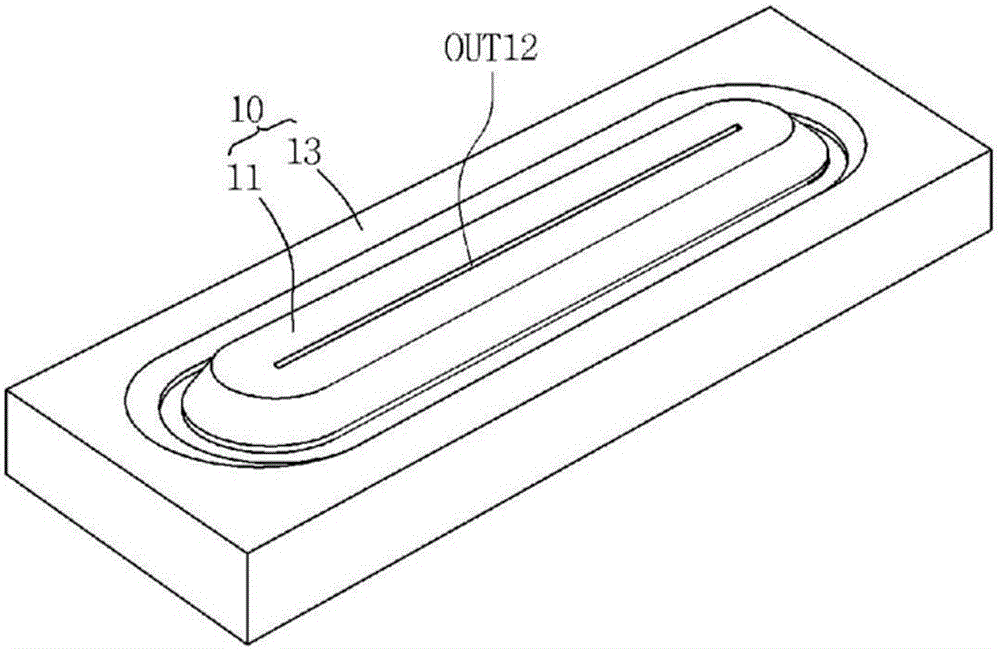
[0082] Figure 2a , 2b are perspective and sectional views showing a second embodiment of the ion source of the present invention.

[0083] Such as Figure 2a , 2b As shown, in the second embodiment, an inner front gas ejection portion OUT12 that opens toward the direction of the substrate is formed in the inner gas injection portion 21, and the inner side gas ejection portion OUT12 that opens toward the accelerated closed-loop direction of the first embodiment may not be included. OUT11.

[0084] The inner front gas ejection portion OUT12 may be formed along the longitudinal direction of the inner magnetic pole 11 . One side of the inner front gas ejection portion OUT12 communicates with the inner gas dispersion portion DIS11, and the other side communicates with the substrate direction. The inner front gas ejection portion OUT12 has a smaller cross section than the inner gas dispersion portion DIS11, and therefore ejects the gas in the inner gas dispersion portion DIS11...


PUM


Abstract

An ion source comprises a magnetic field unit and an electrode. One side of the magnetic field unit, which faces an object to be treated, is open, while the other side thereof is closed. The magnetic field unit has, on one side that is open, an inner magnetic pole and an outer magnetic pole arranged to be spaced from each other, and a magnetic core is connected to the other side of the magnetic field unit, which is closed, thereby forming an acceleration closed loop for plasma electrons on one side thereof, which is open. The inner magnetic pole has a gas injection unit penetrating the interior thereof, thereby supplying a gas towards the acceleration closed loop. The electrode is arranged below the acceleration closed loop inside the magnetic field unit to be spaced from the magnetic field unit.

Description

technical field [0001] The present invention relates to an ion source, in particular, an ion source with a gas injection portion on a magnetic pole. Background technique [0002] Ion source (ion source) is effectively used for substrate modification or sputter coating. The ion source forms a closed drift loop (closed drift loop) with electrodes and magnetic poles, and is a structure that moves electrons at high speed along the loop. In the closed loop of electron movement, the ionization gas, which is the gas for ion generation, is continuously supplied from the outside of the process chamber to the inside of the process chamber. [0003] US Patent No. 7,425,709 is equipped with an independent gas supply pipe and gas diffusion components for supplying ionized gas to the inside of the ion source from the outside. As mentioned above, most of the traditional ion sources supply ionized gas from the rear end of the ion source, generate plasma inside the ion source, and use the ...

Claims


Application Information

Patent Timeline
Patent Type & Authority Applications(China)
IPC IPC(8): H01J27/02
CPCH01J27/02H01J37/32422H01J37/32449H01J37/08
Inventor 黄允硕许闰成
Owner 发仁首路先株式会社
Why Eureka
Try Eureka