
Stereotactic magnetic head, array, and brain neuronal electrical activity interference system

A stereotaxic and interferometric system technology, applied in the field of electromagnetic technology and neuroelectrophysiology, can solve the problems of narrow clinical adaptability and inability to locate very accurately

Active Publication Date: 2017-05-17
臧大维 +1
View PDF4 Cites 2 Cited by
  • Summary
  • Abstract
  • Description
  • Claims
  • Application Information

AI Technical Summary

Problems solved by technology

The advantage of transcranial magnetic stimulation technology is that it is non-invasive, but its disadvantage is that it cannot be positioned very accurately, resulting in a narrow range of clinical adaptation
[0003] In terms of scientific research, the human-brain-computer interface has become a subject of extensive research worldwide, and the main research direction is how to non-invasively obtain high-precision, high-sensitivity and real-time EEG and MEG signals for analysis and application. , these studies are only the one-way interface research of human brain information to computer
However, the research and practical application of how to transmit information from the computer to the brain in a non-invasive way and act on nerve cells is almost blank. Most of the existing related research and applications are invasive. It is achieved by implanting electrodes on the surface of the cortex, but these methods are invasive. Due to the great risk of human brain surgery, all these methods are still in the experimental stage, and it will take a long time to be promoted to the clinic.

Method used


Image

  • Stereotactic magnetic head, array, and brain neuronal electrical activity interference system
  • Stereotactic magnetic head, array, and brain neuronal electrical activity interference system
  • Stereotactic magnetic head, array, and brain neuronal electrical activity interference system

Examples


Embodiment Construction

[0027] Embodiments of the present invention are described in further detail below in conjunction with the accompanying drawings:

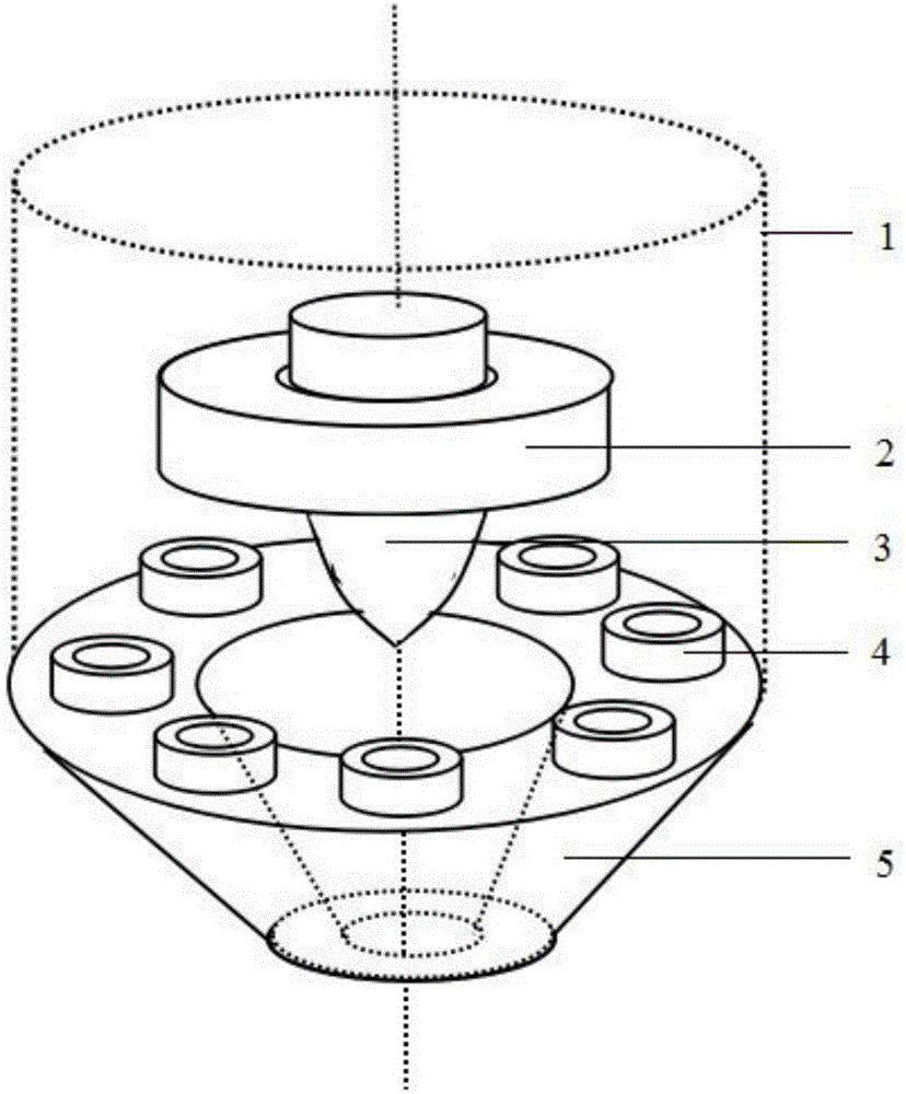
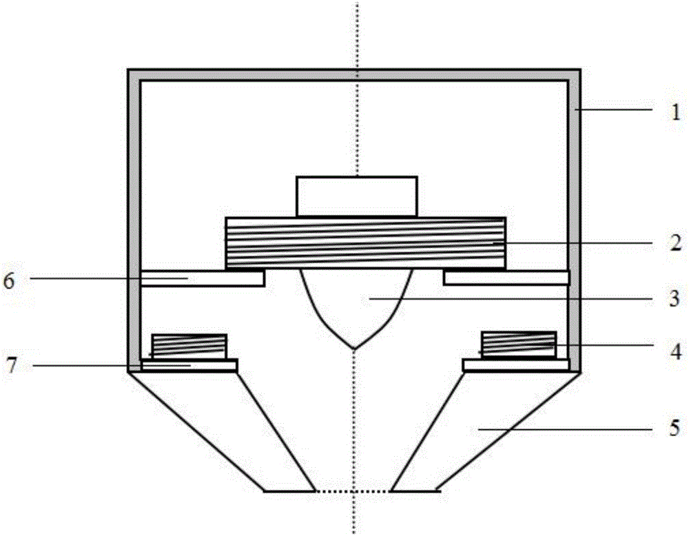
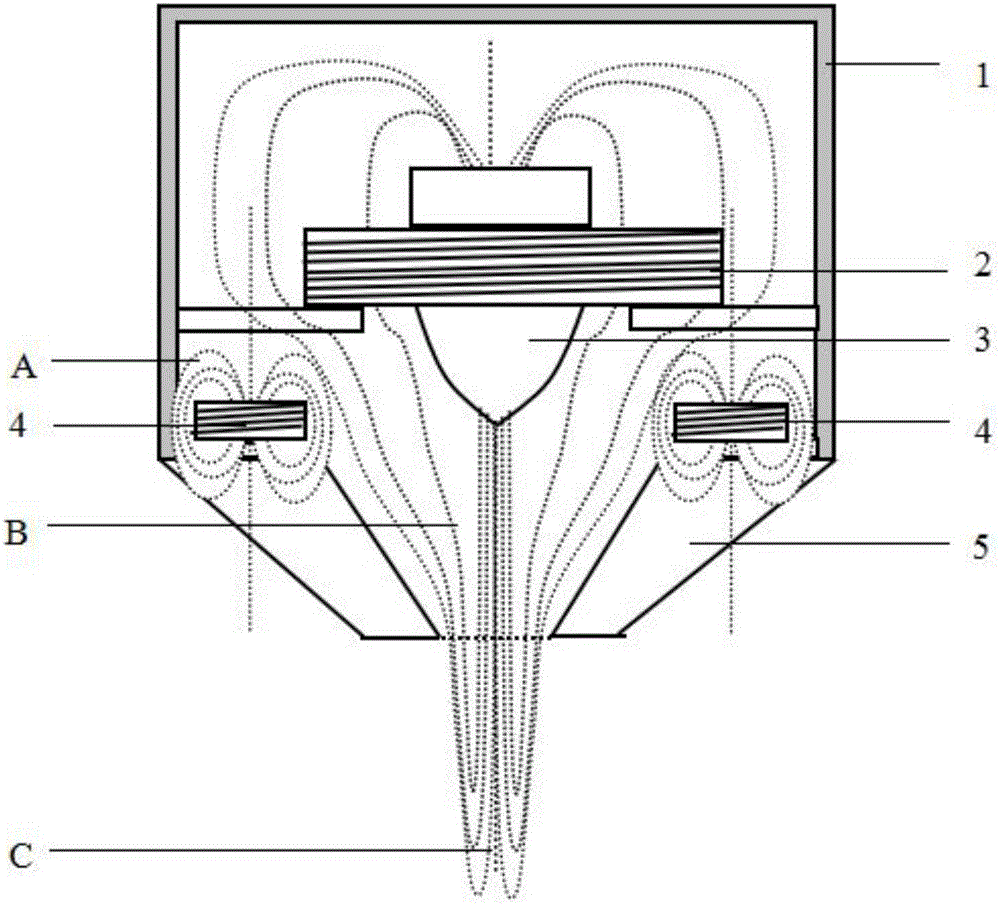
[0028] A stereotactic head, such as Figure 1 to Figure 5 As shown, the stereotaxic magnetic head housing 1, the pulsed magnetic field coil 2, the pulsed magnetic field guiding column 3, a plurality of magnetic field stereotaxic control coils 4, the magnetic field guiding conical ring 5, the pulsed magnetic field coil support plate 6, and the magnetic field stereotaxic control coil support plate 7 composition. The pulsed magnetic field guiding column is set in the center of the pulsed magnetic field coil, and the pulsed magnetic field coil is installed on the upper end of the stereotaxic magnetic head shell through the pulsed magnetic field coil support plate, and the pulsed magnetic field coil is connected to the pulsed magnetic field coil through the pulsed magnetic field coil connecting wire D On the control unit; the plurality of magnetic fiel...


PUM


Abstract

The invention relates to a stereotactic magnetic head, an array, and a brain neuronal electrical activity interference system. The technical characteristics are that the stereotactic magnetic head comprises a stereotactic magnetic head shell, a pulse magnetic field coil, a pulse magnetic field guide column, a plurality of magnetic field stereotactic control coils and a magnetic field guide conical ring; the stereoscopic magnetic head array consists of a plurality of stereoscopic magnetic heads; and the system comprises a stereotactic magnetic head array, a pulse magnetic field coil control unit, a magnetic field stereotactic control coil control unit and a central control unit. According to the invention, the membrane potential of the cerebral cortical nerve cells can be changed and an induced current can be produced by applying the pulse magnetic field to the brain; the control function of the electrical activity of the cerebral cortical nerve cells can be realized by controlling the direction of the pulse magnetic field and the magnetic induction intensity; and the invention can be widely used in noninvasive artificial vision, artificial hearing, control treatment of abnormal cerebral cortex electrical activity and abnormal neuronal reshaping and the like.

Description

technical field [0001] The invention belongs to the field of electromagnetic technology and neuroelectrophysiological technology, in particular to a stereotactic magnetic head and an array, and a system for interfering electrical activity of brain nerve cells. Background technique [0002] At present, there are very few projects in which electromagnetic technology is actually applied clinically, such as transcranial magnetic stimulation approved by the US FDA in 2008 for the treatment of drug-resistant depression. The advantage of transcranial magnetic stimulation technology is that it is non-invasive, but its disadvantage is that it cannot be positioned very accurately, resulting in a narrow range of clinical adaptation. [0003] In terms of scientific research, the human-brain-computer interface has become a subject of extensive research worldwide, and the main research direction is how to non-invasively obtain high-precision, high-sensitivity and real-time EEG and MEG sig...

Claims


Application Information

Patent Timeline
IPC IPC(8): A61N2/04
Inventor 郑勇臧大维
Owner 臧大维
Learn More