Centrifugal soil remediation device

A centrifugal, soil technology, used in centrifuges, restoration of polluted soil, centrifuges with rotating drums, etc., can solve the problems of low land treatment efficiency and slow screening speed, and achieve fine and uniform mixing. high degree of effect

Inactive Publication Date: 2017-05-17
CHENGDU KECHUANGCHENG TECH
View PDF0 Cites 2 Cited by
  • Summary
  • Abstract
  • Description
  • Claims
  • Application Information

AI Technical Summary

Problems solved by technology

Manual screening is too slow, and the efficie

Method used


Image

  • Centrifugal soil remediation device
  • Centrifugal soil remediation device
  • Centrifugal soil remediation device

Examples


Embodiment 1

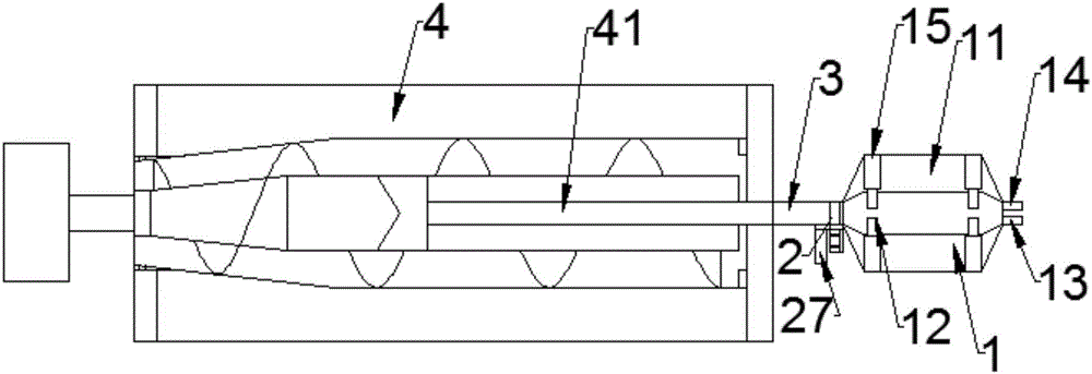
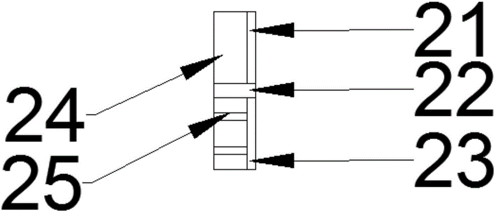
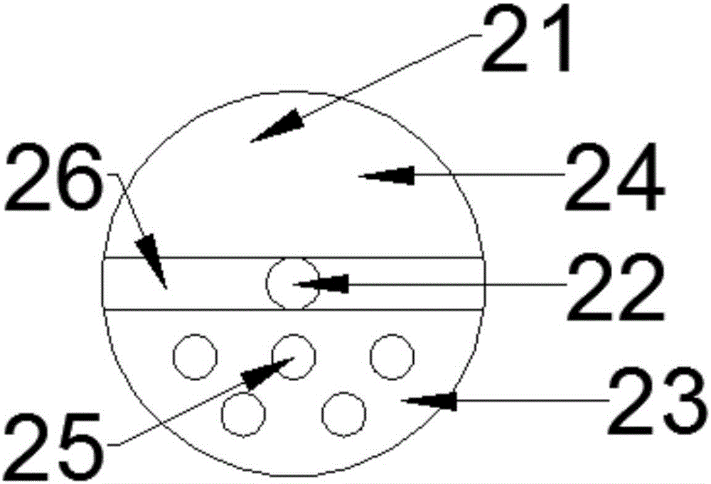
[0020] This embodiment combines figure 1 , figure 2 and image 3 As shown, a centrifugal soil treatment equipment includes a centrifuge 4, a material pipe 3, a filter screen 2, and an ultrasonic agitator 1 connected in sequence, and the ultrasonic agitator 1 is a functional chamber 11 from the outside to the inside. , stirring chamber 12, ultrasonic agitator 1 also includes ultrasonic generator 15 arranged in functional chamber 11, feed pipe 13 and liquid inlet pipe 14 connected to one end of stirring chamber 12; described filter screen 2 includes circular screen mesh 21. A rotating shaft 22 arranged in the center of the circular screen 2, a rotary motor 27 connected to the rotating shaft 22, a partition 26 is arranged in the middle of the filter screen 2, and the partition 26 divides the circular screen 2 into use chambers 24 and 26. The cleaning chamber 23 is connected to the material pipe 3 and the stirring chamber 12 by the two ends of the use chamber 24 . The cleaning ...

Embodiment 2

[0023] This embodiment is further improved based on Embodiment 1, such as figure 1 As shown, the stirring chamber 12, the filter screen 2, the material pipe 3, and the centrifugal pipe 41 are all connected by threads.

[0024] During use, the stirring chamber 12, the filter screen 2, the material pipe 3, and the centrifuge tube 41 are all connected by threads, so that the filter screen 2 and the material pipe 3 are detachable. When they are stuck and cannot be cleaned automatically, use The operator can keep the device working by manual cleaning or replacement.

Embodiment 3

[0026] This embodiment is further improved based on Embodiment 2, combined with figure 2 and image 3 As shown, the mesh aperture of the circular screen 21 is 50um.

[0027] During use, the mesh aperture of the circular screen 21 should not be too large nor too small. Since the material is a mixture of soil and liquid, its viscous force is extremely high. If the mesh aperture is too small, the flow rate of the material is slow and the work efficiency is reduced. , the sieve aperture is large so that smaller diameter stones, etc. can pass through the circular screen 21, thereby damaging the centrifuge.


PUM


Abstract

The invention discloses a soil remediation device, and in particular relates to a centrifugal soil remediation device. The centrifugal soil remediation device comprises an ultrasonic stirrer, a filter sieve and a charge pipe, wherein the ultrasonic stirrer is sequentially provided with a functional chamber and a stirring chamber from outside to inside; the ultrasonic stirrer also comprises an ultrasonic generator arranged in the functional chamber, and a feed pipe and a liquid inlet pipe which are connected with one end of the stirring chamber; the filter sieve comprises a circular screen, a rotating shaft arranged in the center of the circular screen, and a rotary motor connected with the rotating shaft; a spacer plate is arranged in the middle of the filter sieve, and the circular screen is divided into a use cavity and a cleaning cavity by the spacer plate; the use cavity is connected with the charge pipe and the stirring chamber in a matching way, and the cleaning cavity is internally provided with a flushing device; the other end of the charge pipe is connected with a centrifugal tube of a centrifuge. The centrifugal soil remediation device is capable of automatically cleaning large objects and residual branches and leaves in soil, so as to prevent damage and channel blockage caused by the large objects and the residual branches and leaves which enter the centrifuge.

Description

technical field [0001] The invention relates to a soil treatment device, in particular to a centrifugal soil treatment device. Background technique [0002] Soil remediation measures can be divided into three methods: physical, chemical and biological. Among the physical remediation methods, soil remediation through centrifuges is a good choice. However, because the centrifuge has certain requirements for the centrifugal material during use, usually, the particle size of the soil is divided into 4 grades, namely sand (>20um), coarse silt (5-20um), fine silt ( 2-5um) and clay particles (2um), if you put large pieces of hard objects, it is easy to damage the parts inside, so it usually needs to be screened. The manual screening speed is too slow, and the efficiency of land management in an area is quite low. SUMMARY OF THE INVENTION [0003] The purpose of the present invention is: in view of the above problems, the present invention provides a centrifugal soil treatmen...

Claims


Application Information

Patent Timeline
IPC IPC(8): B01F11/02B04B1/20B04B7/16B09C1/00
CPCB04B1/20B04B7/16B09C1/00B01F31/80
Inventor 王明洋蒋星华
Owner CHENGDU KECHUANGCHENG TECH
Why Eureka
Try Eureka