Wire bending equipment

A bending and equipment technology, applied in the field of bending machines, can solve the problems of limited bending radius range, inability to quickly and accurately adjust the bending radius in real time, insufficient flexibility, etc., and achieve the effect of convenient replacement

Inactive Publication Date: 2017-05-17
王坤
View PDF0 Cites 0 Cited by
  • Summary
  • Abstract
  • Description
  • Claims
  • Application Information

AI Technical Summary

Problems solved by technology

[0002] At present, there are various metal wire bending machines on the market, such as steel bar bending machines, pipe bending machines, portable bending machines, etc. Although these bending machines can meet the needs of daily production, they cannot bend materials as desired. That is, the maximum bending angle of these bending machines on the market does not exceed 270°, and most of them can bend 180°
When it is necessary to continuously bend the material into a helical pattern, the bending machine is required to bend the material by 360°, and these existing bending machines are difficult to meet the demand
In addition, the existing bending machines are not flexible enough to adjust the bending radius quickly and accurately in real time, and the range of the adjusted bending radius is also limited to a certain extent

Method used


Image

  • Wire bending equipment
  • Wire bending equipment
  • Wire bending equipment

Examples


Embodiment Construction

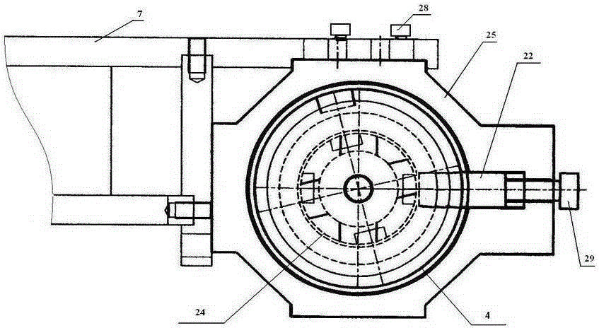
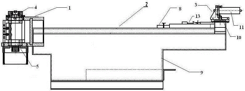
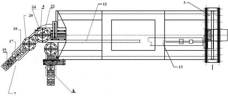
[0027] refer to figure 1 , figure 2 and image 3 As shown, the present invention comprises a machine head 1, a body 2 and a tailstock 3, and the metal wire rod to be bent enters the body 2 through the guide slot hole 21 of the tailstock 3, and after the hydraulic oil cylinder works, the feeding device 13 is in the transmission Rotate under the action of the device 10, the metal wire moves forward after passing through the feeding device 13 and the guide rail mechanism 8, and the front end of the metal wire enters the guide rail groove 12 driven by the feeding device 13, and then enters the arm mold 20 and the bending die 4 In the mold formed, at this moment, the bending die 4 rotates, and the fixed rotating arm 6 and the rotating arm 7 are in a parallel state. After the front end of the metal wire passes through the mold formed by the arm die 20 and the bending die 4, the hydraulic cylinder stops, and then Adjust and fix the fastening mechanism 17 on the sliding bracket 18 ...


PUM


Abstract

The invention provides wire bending equipment which comprises a machine head, a machine body and a tail base, wherein the machine head is positioned on the front part of a bender, and comprises a drive device, a bending mould, a fixed rotary arm, a rotary arm and a rotary arm angle bracket; the fixed rotary arm is fixedly arranged on a bracket of the machine body; the rotary arm is fixedly arranged on a bearing base; power is provided by the drive device, a fixed supporting frame and a slide supporting frame are arranged on the drive device; the slide supporting frame is equipped with a slide oil cylinder; the slide oil cylinder can drive the slide supporting frame to move on the fixed supporting frame; one end of the slide supporting frame is equipped with an arm mould which is fixedly arranged on the slide supporting frame through a fastening mechanism; the machine body comprises a guide rail mechanism and a bracket; the guide rail mechanism is mounted on the upper part of the bracket; one end of the guide rail mechanism is connected with the tail base; the other end of the guide rail mechanism is connected with the machine head through a guide rail slot included in the guide rail mechanism; and after the metal wire put into the guide rail slot through the tail base, a feeding device included in the guide rail mechanism is used for feeding forwards.

Description

technical field [0001] The invention relates to the technical field of bending machines, in particular to wire bending equipment. Background technique [0002] At present, there are various metal wire bending machines on the market, such as steel bar bending machines, pipe bending machines, portable bending machines, etc. Although these bending machines can meet the needs of daily production, they cannot bend materials as desired. That is, the maximum bending angle of these bending machines on the market does not exceed 270°, and most of them can bend 180°. When it is necessary to continuously bend the material into a spiral pattern, the bending machine is required to be able to bend the material by 360°, and these existing bending machines are difficult to meet the demand. In addition, the existing bending machines are not flexible enough to quickly and accurately adjust the bending radius in real time, and the range of the adjusted bending radius is also limited to a cert...

Claims


Application Information

Patent Timeline
IPC IPC(8): B21F1/00
CPCB21F1/00
Inventor 王坤
Owner 王坤
Why Eureka
Try Eureka