Convergence strip lap welding machine

A welding machine and machine base technology, applied in the field of photovoltaic ribbon automatic welding machine, can solve the problems of unguaranteed quality, low work efficiency, and increased cost, and achieve the effects of solving cumbersome operations, improving production efficiency, and improving quality

Active Publication Date: 2017-05-17
苏州羿驰辉科技有限公司
View PDF10 Cites 3 Cited by
  • Summary
  • Abstract
  • Description
  • Claims
  • Application Information

AI Technical Summary

Problems solved by technology

[0002] Ribbon is the carrier used to connect cells in solar cells. It plays a conductive role. The main component is copper. The welding ribbon is cut to the required length, and the cutting is performed by a welding ribbon cutting machine. The welding ribbon cutting machine currently used, after the welding ribbon is cut, it must be manually controlled to

Method used


Image

  • Convergence strip lap welding machine
  • Convergence strip lap welding machine
  • Convergence strip lap welding machine

Examples


Embodiment Construction

[0023] It should be understood that the specific embodiments described here are only used to explain the present invention, not to limit the present invention.

[0024] The following will clearly and completely describe the technical solutions in the embodiments of the present invention with reference to the accompanying drawings in the embodiments of the present invention. Obviously, the described embodiments are only part of the embodiments of the present invention, not all of them. Based on the embodiments of the present invention, all other embodiments obtained by persons of ordinary skill in the art without creative efforts fall within the protection scope of the present invention.

[0025] It should be noted that all directional indications (such as up, down, left, right, front, back...) in the embodiments of the present invention are only used to explain the relationship between the components in a certain posture (as shown in the accompanying drawings). Relative positi...


PUM

PropertyMeasurementUnit
Thicknessaaaaaaaaaa

Abstract

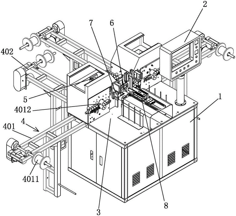
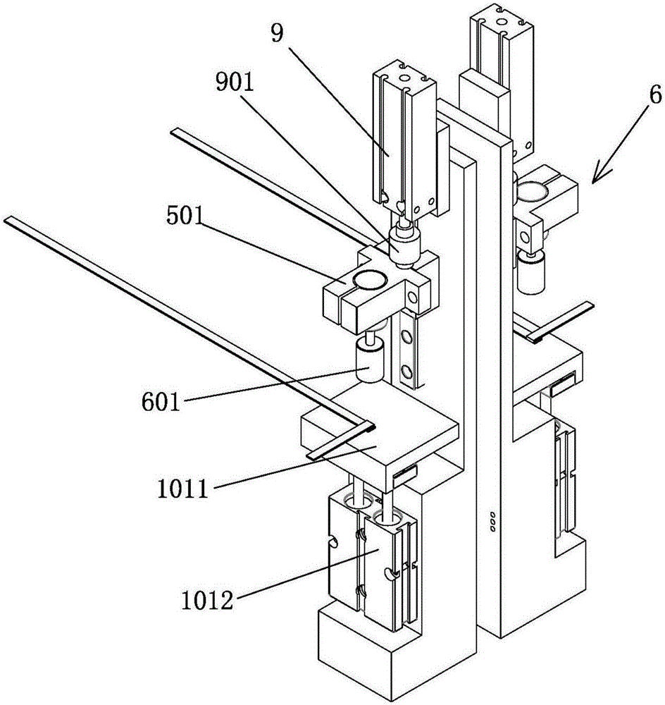
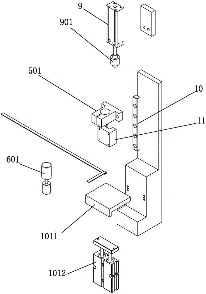
The invention discloses a convergence strip lap welding machine, which comprises a base. A control device and a workbench are arranged on the base; a material conveying device, a heating device, a welding device, a cutting device and a collecting device are arranged on the workbench and are controlled by the control device to run; the material conveying device comprises a first conveying device and a second conveying device and is used for loading and conveying materials; the welding device comprises a welder and a pressure controller; the welder is connected with the pressure controller; the pressure controller controls welded pressure output by the welder and is used for welding two input material lapped butt ends; the heating device is connected with the welding device and is used for heating welding tin of the welding device; the cutting device is provided with a cutting die and a first drive device; the first drive device drives the cutting die to cut off a welded material; and the collecting device is arranged under the welding device and is used for collecting welded finished product materials. The convergence strip lap welding machine has the advantages of automatic welding, simplicity and convenience in operation, and high production efficiency.

Description

technical field [0001] The invention relates to the technical field of welding machines, in particular to an automatic welding machine for photovoltaic ribbons. Background technique [0002] Ribbon is the carrier used to connect cells in solar cells. It plays a conductive role. The main component is copper. The welding ribbon is cut to the required length, and the cutting is performed by a welding ribbon cutting machine. The welding ribbon cutting machine currently used, after the welding ribbon is cut, it must be manually controlled to a certain amount to stop cutting, and the welding ribbon will be cut. The ribbons are stored separately according to the quantity, and then the ribbons are manually welded to the photovoltaic panel. In this way, there are disadvantages of low work efficiency, and there are human factors, and the quality cannot be guaranteed, resulting in an increase in cost. Contents of the invention [0003] The purpose of the present invention is to solv...

Claims


Application Information

Patent Timeline
IPC IPC(8): B23K1/00B23K3/04B23K3/08H01L31/18
CPCB23K1/0008B23K3/04B23K3/08H01L31/188Y02P70/50
Inventor 朱小波谭伟新钟建平李燕青
Owner 苏州羿驰辉科技有限公司
Why Eureka
Try Eureka