Projection welding method for piston rod and connecting ring of automobile shock absorber

A welding method and piston rod technology, applied in welding equipment, vehicle parts, resistance welding equipment, etc., can solve problems such as hidden dangers of piston rod quality, failure of sealing effect, oil leakage, failure of shock absorbers, etc. Improve product quality and increase the effect of contact area

Active Publication Date: 2019-12-20
SICHUAN NINGJIANG SHANCHUAN MACHINERY
View PDF7 Cites 0 Cited by
  • Summary
  • Abstract
  • Description
  • Claims
  • Application Information

AI Technical Summary

Problems solved by technology

[0004] However, since the thin neck of the piston rod 9 is in clearance fit with the inner hole of the dustproof cover 6, under the premise of adopting the projection welding method, the clamping electrode 7 needs to conduct electricity by clamping the piston rod 9 to complete the projection welding process. This increases the possibility of the piston rod 9 being pinched, and when the clamping surface of the clamping electrode 7 adheres to metal or impurities, the piston rod 9 is more prone to serious burns or slight sparks and other quality defects , the quality defects on the surface of this type of piston rod will easily cause the lip of the oil seal of the shock absorber to be scratched and damaged during the use of the shock absorber, and the sealing effect will fail prematurely and oil leakage will cause the shock absorber to fail
Relevant R&D personnel try to ensure the manufacturing accuracy of projection welding electrodes, the selection of electrode materials, the cleanliness of piston rods before welding, and the effective and regular maintenance or replacement of electrodes during use under the premise of original technology and equipment. Make a fuss about other aspects, solidify into a standard process and control it. Although there are obvious effects, there are always potential quality problems in the piston rod after projection welding, which cannot fundamentally ensure the expected service life of the shock absorber.

Method used


Image

  • Projection welding method for piston rod and connecting ring of automobile shock absorber
  • Projection welding method for piston rod and connecting ring of automobile shock absorber
  • Projection welding method for piston rod and connecting ring of automobile shock absorber

Examples


Embodiment 1

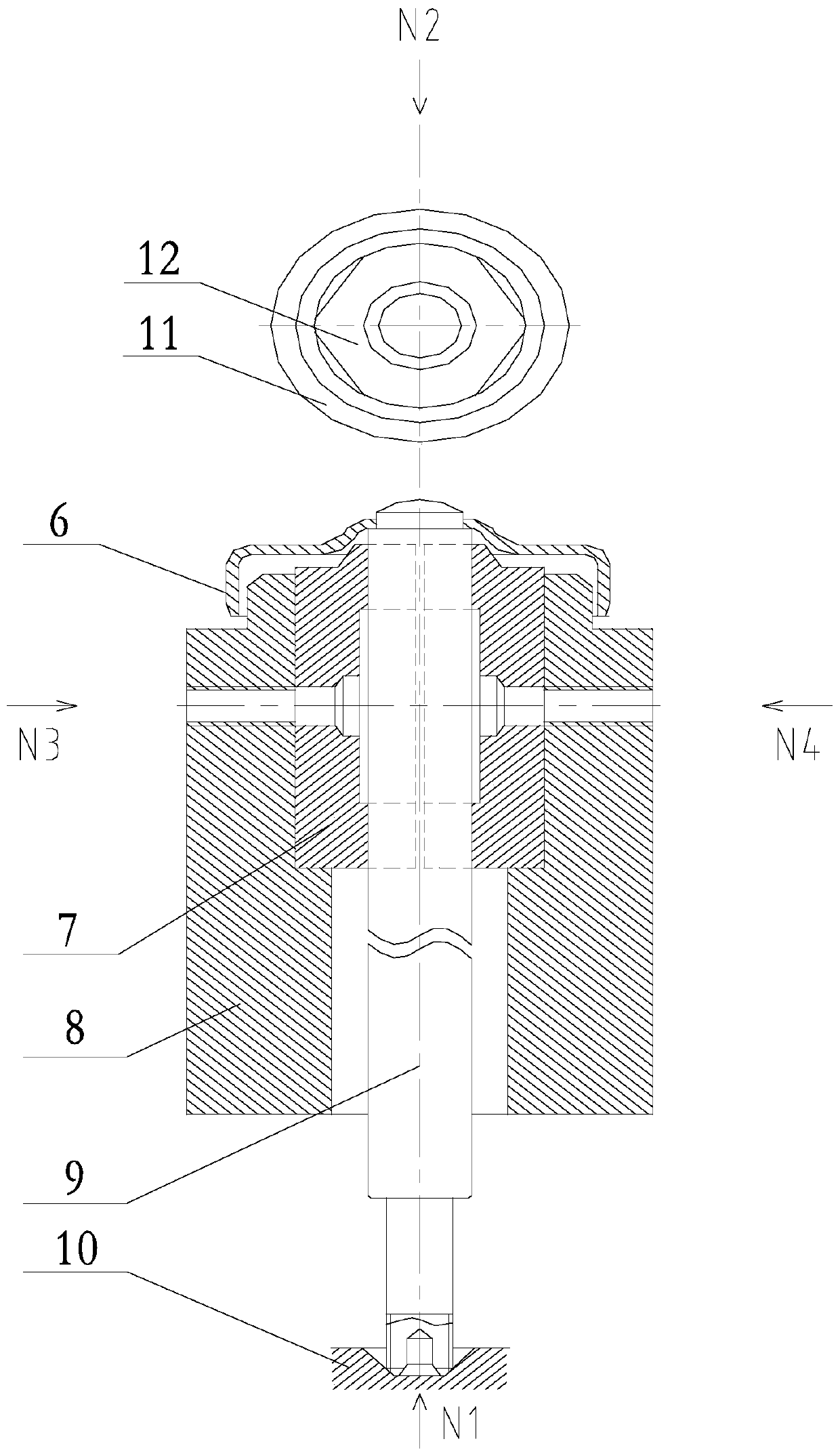
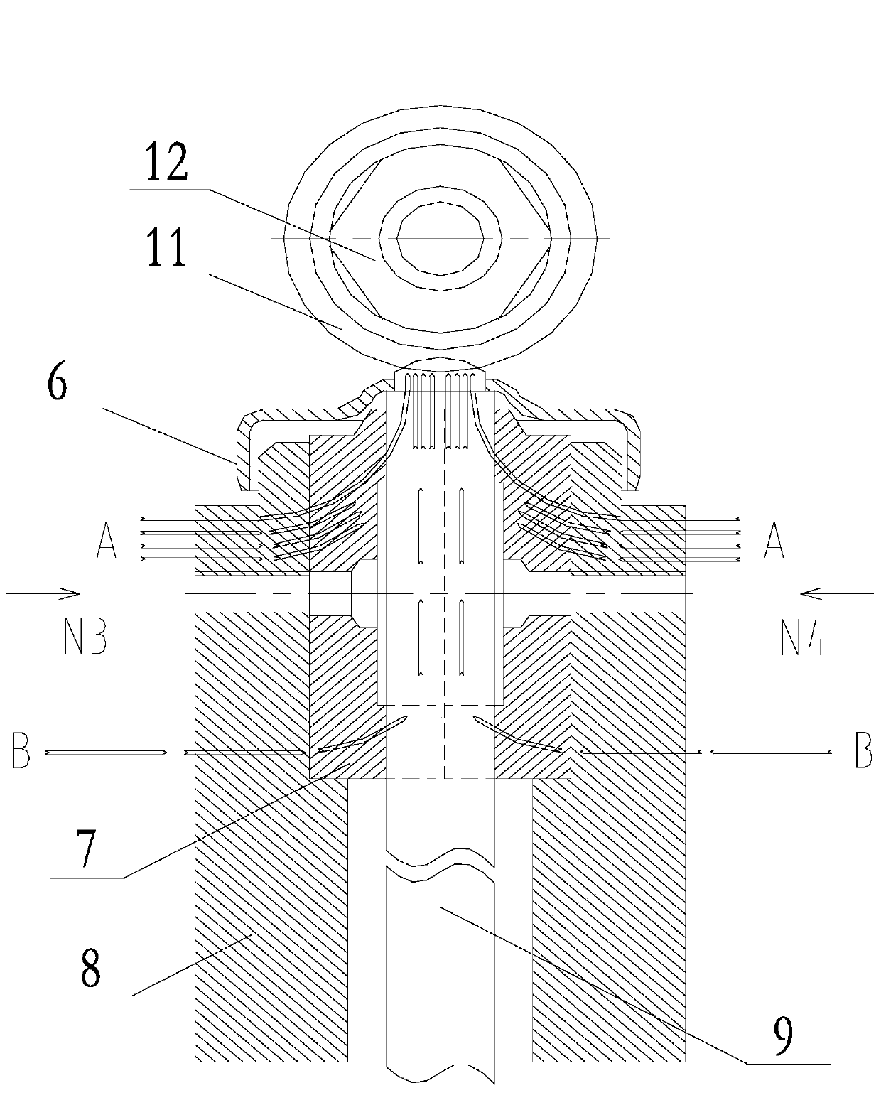
[0037] Such as Figure 5-6 As shown, this embodiment includes the following steps:

[0038] A. Fix the dust cover 6 on the upper end of the piston rod 9, then;

[0039] B, fixing the connecting ring 11 on the positioning electrode 12;

[0040] C. Send the piston rod 9 into the welding position and fix it;

[0041] D Utilize at least two clamping electrodes 13 to clamp the outer peripheral wall of the dustproof cover 6, and push the positioning electrodes 12 to move down until the lower part of the connecting ring 11 contacts the upper end of the piston rod 9;

[0042] E. After the connecting ring 11 contacts with the upper end of the piston rod 9, a welding circuit is formed to weld the piston rod 9 and the connecting ring 11. In the existing projection welding process, by applying forces N3 and N4 to the side walls of the two clamping electrodes 7, the piston rod 9 is stably clamped and fixed, and the electrode holder 8, the electrode 7 and the piston rod 9 together form a...

Embodiment 2

[0046] Such as Figure 5 with Image 6 As shown, the piston rod 9 includes a main body and a thin neck section connected to the upper end of the main body, and the outer diameter of the thin neck section is smaller than the outer diameter of the main body, and the dustproof cover 6 is arranged on the thin neck paragraph. Piston rod 9 is divided into two parts, namely main body and thin neck section, and the outer diameter of thin neck section is less than the outer diameter of main body, and dustproof cover 6 is fixed on the thin neck section, utilizes the outer diameter between thin neck section and main body The diameter difference ensures that the contact is sufficiently conductive and prevents the clamping electrode 13 from loosening between the dust cover 6 and the thin neck section when the clamping electrode 13 clamps the dust cover 6, thereby improving the quality of projection welding.

[0047] Further, there is an interference fit between the dust cover 6 and the t...

Embodiment 3

[0050] Such as Figure 7As shown, a flange 15 coaxial with the inner hole of the dustproof cover 6 is arranged on the top of the dustproof cover 6 , and the inner diameter of the flange 15 is the same as the inner diameter of the inner hole of the dustproof cover 6 . A flange 15 is provided on the dustproof cover 6, thereby increasing the contact area between the dustproof cover 6 and the interference fit area of ​​the thin neck section. The gradually increasing projection welding fusion area between the rings, after the welding circuit is formed, quickly generates a large amount of resistance heat at the place with the largest resistance in the circuit, so that the bottom of the connecting ring 11, the top of the dustproof cover 6 and the thin neck section The ends reach the temperature range where they can be fused together, and under the extrusion action of the pressure generated by the downward movement of the positioning electrode 12, the melting metal grains on the conne...


PUM

PropertyMeasurementUnit
lengthaaaaaaaaaa
lengthaaaaaaaaaa
diameteraaaaaaaaaa

Abstract

The invention discloses a projection welding method of an automobile shock absorber piston rod and a connecting ring. The method comprises the following steps that A, a dustproof cover is fixed to the upper end of the piston rod; B, the connecting ring is fixed to a positioning electrode; C, then the piston rod is conveyed to the welding station and fixed; D, the outer circumferential wall of the dustproof cover is clamped through at least two clamping electrodes, and the positioning electrode is pushed to move downwards till the lower portion of the connecting ring makes contact with the upper end of the piston rod; and E, a welding loop is formed after the connecting ring makes contact with the upper end of the piston rod so that welding between the piston rod and the connecting ring can be carried out. The mode that a clamping electrode directly acts on the outer circle surface of the piston rod in an existing projection welding technique is omitted, that is, the working surface of the piston rod is completely prevented from directly making contact with a projection welding electrode, thus, no clamping conductive area can be formed on the piston rod, and the piston rod is protected against pinching, slight ignition, severe burns and the like.

Description

technical field [0001] The invention relates to a car rear shock absorber, in particular to a projection welding method for a piston rod and a connecting ring of the automobile shock absorber. Background technique [0002] The telescopic shock damper is mainly used to suppress the shock when the spring rebounds after absorbing the shock and the impact from the road. When passing through uneven roads, although the shock-absorbing spring can filter the vibration of the road surface, the spring itself will reciprocate, and the shock absorber is used to suppress this spring jumping. The shock absorber on the car usually adopts a cylinder type hydraulic shock absorber, which is mainly composed of an oil seal, a dust cover, a piston rod, a piston valve, a bottom valve, a working cylinder, an oil storage cylinder, and an upper and lower connecting ring. When the valve ends move relative to each other, the hydraulic oil passes through a certain channel to generate throttling, and t...

Claims


Application Information

Patent Timeline
Patent Type & Authority Patents(China)
IPC IPC(8): B23K11/14B23K11/34
CPCB23K11/14B23K11/34B23K2101/006
Inventor 石建德唐旭东朱廷焕
Owner SICHUAN NINGJIANG SHANCHUAN MACHINERY
Why Eureka
Try Eureka