
An automatic polishing and chamfering machine for a table

An automatic polishing and chamfering machine technology, used in grinding/polishing equipment, grinding drive devices, grinding machine parts, etc., can solve the problem of unsatisfactory polishing and chamfering effect, uneven grinding degree, The effect is not very good, etc., to achieve the effect of simple structure, improving effect and ensuring consistency

Active Publication Date: 2018-10-23
广东顺德恒丽宝商用厨具有限公司
View PDF6 Cites 0 Cited by
  • Summary
  • Abstract
  • Description
  • Claims
  • Application Information

AI Technical Summary

Problems solved by technology

[0003] Most of the existing table polishing chamfers are polished by artificial sandpaper, which is time-consuming and laborious, and the grinding effect is not very good, and the degree of polishing is uneven. Therefore, there have been some equipment for table polishing. Most of the table grinding equipment adopts a circularly rotating abrasive belt and a clamping device that tilts and feeds the table, which is prone to loosening of the abrasive belt and complicated tightening of the abrasive belt, which can easily damage the abrasive belt after long-term work belt, resulting in unsatisfactory polishing and chamfering effect

Method used


Image

  • An automatic polishing and chamfering machine for a table
  • An automatic polishing and chamfering machine for a table
  • An automatic polishing and chamfering machine for a table

Examples


Embodiment Construction

[0031] In order to enable those skilled in the art to better understand the technical solution of the present invention, the present invention will be described in detail below in conjunction with the accompanying drawings. The description in this part is only exemplary and explanatory, and should not have any limiting effect on the protection scope of the present invention. .

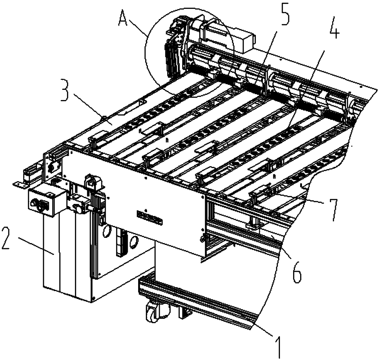
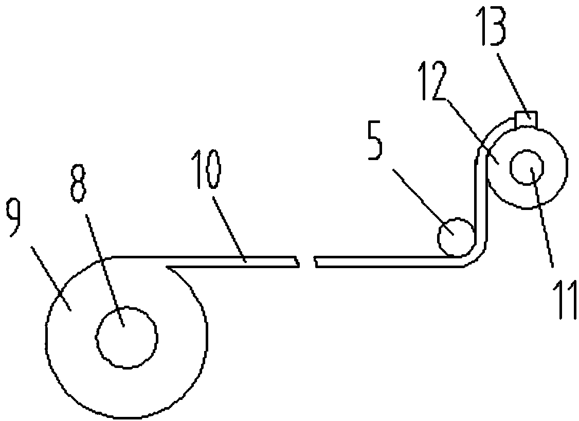
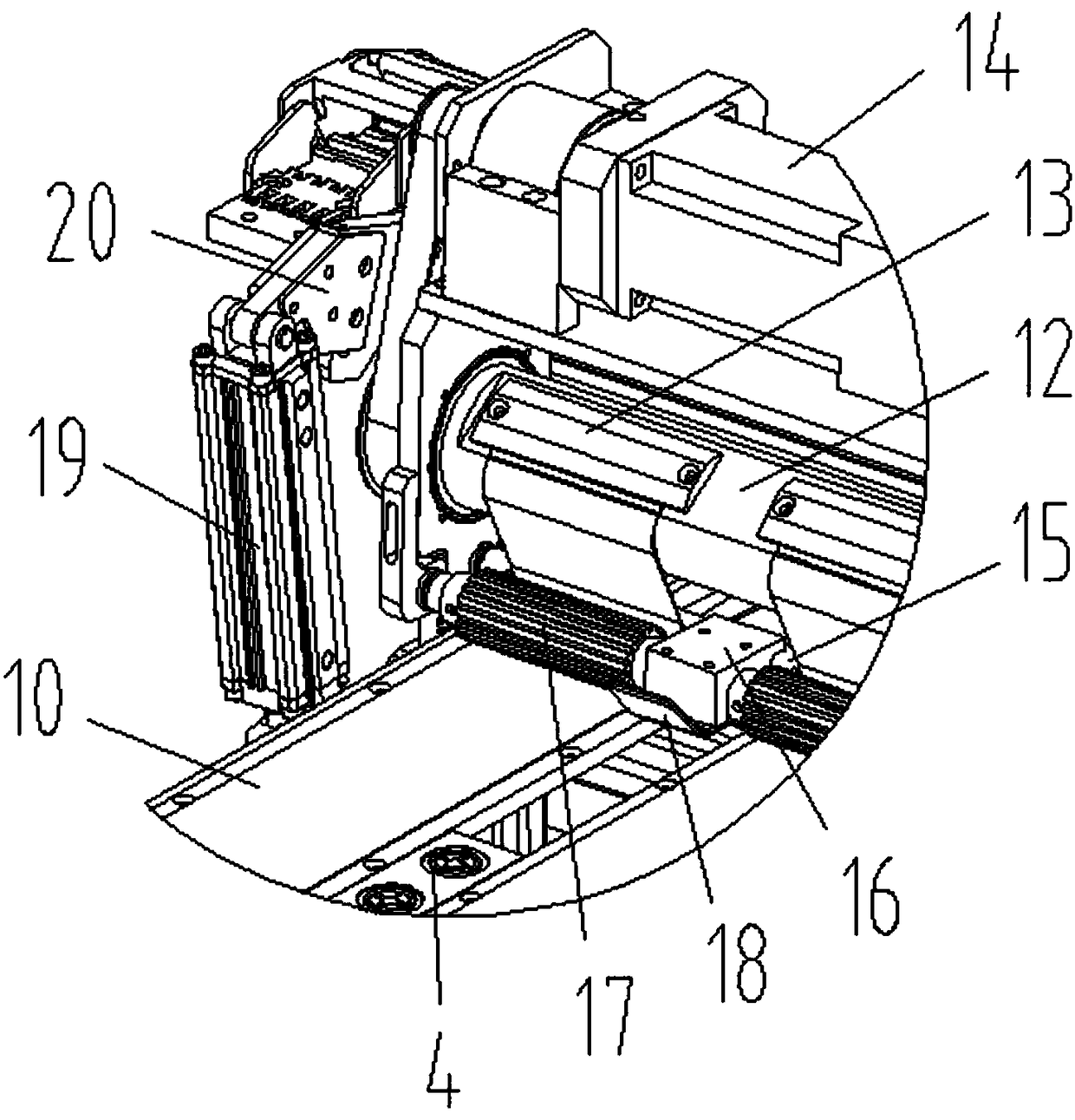
[0032] Such as Figure 1-Figure 6 As shown, the specific structure of the present invention is: a kind of automatic polishing and chamfering machine of table top, it comprises frame 1 and power distribution control box 2, described frame 1 is uniformly provided with polishing and chamfering device 3, The polishing and chamfering device 3 includes an abrasive belt 10 inclined upward from front to back arranged on the frame 1, and a feeder that cooperates with the table board and makes the table board horizontally feed forward and backward is provided in the gap between adjacent abrasive belts 10. The f...


PUM


Abstract

The invention relates to an automatic polishing chamfering machine of a table board. The automatic polishing chamfering machine comprises a rack and a distribution control box. The rack is uniformly provided with polishing chamfering devices, each polishing chamfering device comprises an abrasive belt which is arranged on the rack and is upwards inclined from front to back, and a feeding mechanism matched with the table board and making the table board be fed in a front-rear horizontal manner is arranged in a gap between every two adjacent abrasive belts; and each feeding mechanism comprises a feeding device arranged on the rack and being capable of performing front-rear feeding, each feeding device is provided with a feeding clamper matched with the table board, and the feeding devices and the feeding clampers are connected to the distribution control box. According to the automatic polishing chamfering machine of the table board, the abrasive belts which are arranged in an inclined manner are adopted as the polishing chamfering devices in cooperation with the feeding mechanisms capable of making the table board be fed in a horizontal front-rear manner to achieve fixed-angle chamfering of the table board, chamfering efficiency is improved, the situation that abrasive belts are loose is avoided, and consistency of polishing chamfering is guaranteed.

Description

technical field [0001] The invention relates to the field of plate processing equipment, in particular to an automatic polishing and chamfering machine for a table. Background technique [0002] Tables are commonly used daily necessities, and most of them are made of wooden table boards. During the processing of wooden table boards, the four sides of the wooden table boards need to be polished and chamfered so that they will not be scratched by the human body. [0003] Most of the existing table polishing chamfers are polished by artificial sandpaper, which is time-consuming and laborious, and the grinding effect is not very good, and the degree of polishing is uneven. Therefore, there have been some equipment for table polishing. Most of the table grinding equipment adopts a circularly rotating abrasive belt and a clamping device that tilts and feeds the table, which is prone to loosening of the abrasive belt and complicated tightening of the abrasive belt, which can easily...

Claims


Application Information

Patent Timeline
Patent Type & Authority Patents(China)
IPC IPC(8): B24B21/00B24B21/18B24B21/20B24B47/20B24B41/06
CPCB24B19/24B24B21/002B24B21/006B24B21/18B24B21/20B24B41/06B24B47/20
Inventor 邓君徐红娇何楚亮
Owner 广东顺德恒丽宝商用厨具有限公司
Learn More