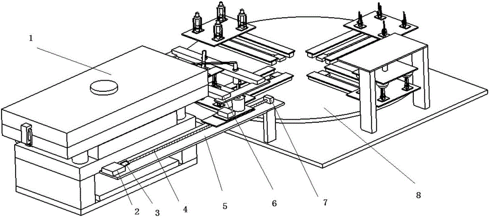
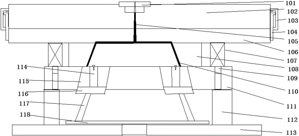
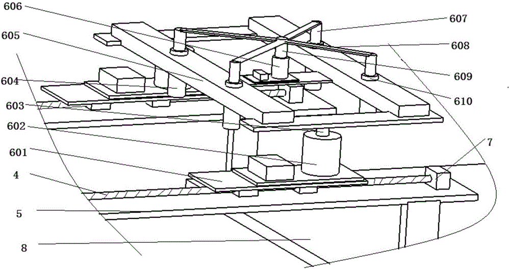
Assembly mechanism for forming and assembling

A technology of assembly mechanism and sliding mechanism, which is applied in the field of assembly mechanism for molding assembly, can solve the problems of labor cost, increase of production process, and decrease of yield rate, etc., and achieve the effect of reducing workload, convenient and firm fixing, and improving yield rate

Inactive Publication Date: 2017-05-17
天津格林特科技有限公司
View PDF0 Cites 2 Cited by
  • Summary
  • Abstract
  • Description
  • Claims
  • Application Information

AI Technical Summary

Problems solved by technology

[0002] With the development of society and the advancement of science and technology, people have found that injection molded bearings are more practical than metal bearings, have a wider range of applications, and are more durable. In some cases, shafts and gears do not need to be integrally molded, but need to be separated Injection molding, or the case where the gear is plastic and the shaft is metal, it needs to be processed and molded separately, and then manually assembled, which leads to an increase in the production process and labor costs. It is often easy to cause damage to plastic parts and reduce the yield. In view of this situation, the present invention provides an assembly mechanism for forming and assembling. The forming of the gear and the assembly of the shaft are carried out together, which reduces the workload and assembly time of manual assembly. , reduce production costs, and at the same time ensure the integrity of the gear production and assembly process, easy to take out, and will not damage the workpiece

Method used


Image

  • Assembly mechanism for forming and assembling
  • Assembly mechanism for forming and assembling
  • Assembly mechanism for forming and assembling

Examples


Embodiment Construction

[0023] It should be noted that, in the case of no conflict, the embodiments of the present invention and the features in the embodiments can be combined with each other.

[0024] In describing the present invention, it should be understood that the terms "center", "longitudinal", "transverse", "upper", "lower", "front", "rear", "left", "right", " The orientations or positional relationships indicated by "vertical", "horizontal", "top", "bottom", "inner" and "outer" are based on the orientations or positional relationships shown in the drawings, and are only for the convenience of describing the present invention and Simplified descriptions, rather than indicating or implying that the device or element referred to must have a particular orientation, be constructed and operate in a particular orientation, and thus should not be construed as limiting the invention. In addition, the terms "first", "second", etc. are used for descriptive purposes only, and should not be understood ...


PUM


Abstract

The invention provides an assembly mechanism for forming and assembling. The assembly mechanism for forming and assembling comprises a foundation base and a worktable arranged on the foundation base; positioning bases are distributed on the worktable and are connected to the worktable through second sliding mechanisms in a sliding mode; a plurality of positioning grooves uniformly distributed are formed in the positioning bases; supporting rods placed diagonally are arranged on the periphery of each positioning base; clamping hoops are arranged on the positioning grooves; and a plurality of pressing blocks are arranged on the foundation base, are arranged above the positioning grooves and correspond to the positioning grooves respectively. According to the assembly mechanism for forming and assembling, automatic assembly of gears and shafts is completed simply and conveniently, the gears are not prone to get deformed in the assembling process, the assembly yield is increased, meanwhile, the production processing efficiency is improved, and the assembly and disassembly are convenient.

Description

technical field [0001] The invention belongs to the field of injection molding and assembly integrated equipment, and in particular relates to an assembly mechanism for molding and assembly. Background technique [0002] With the development of society and the advancement of science and technology, people have found that injection molded bearings are more practical than metal bearings, have a wider range of applications, and are more durable. In some cases, shafts and gears do not need to be integrally molded, but need to be separated Injection molding, or the case where the gear is plastic and the shaft is metal, it needs to be processed and molded separately, and then manually assembled, which leads to an increase in the production process and labor costs. It is often easy to cause damage to plastic parts and reduce the yield. In view of this situation, the present invention provides an assembly mechanism for forming and assembling. The forming of the gear and the assembly...

Claims


Application Information

Patent Timeline
Patent Type & Authority Applications(China)
IPC IPC(8): B29C69/00B29C45/03B29C45/42B29C45/26B29C65/56
CPCB29C69/00B29C45/0053B29C45/03B29C45/26B29C45/42B29C66/80B29C66/87B29C66/90
Inventor 孙利
Owner 天津格林特科技有限公司
Why Eureka
Try Eureka