Excitation force control system and excitation force control method of intelligent steering vibratory roller

A technology of vibratory road roller and control method, applied in the direction of roads, roads, road repair, etc., can solve the problems of overpressure, low compaction efficiency, and single applicable occasions, etc.

Pending Publication Date: 2017-05-17
SHAANXI JOINTARK MASCH GRP CO LTD
View PDF0 Cites 4 Cited by
  • Summary
  • Abstract
  • Description
  • Claims
  • Application Information

AI Technical Summary

Problems solved by technology

Its disadvantages are: low compaction efficiency, non-adjustable excitation force or small adjustment range, unable to realize real-time monitoring
Its disadvantages are: the compaction excitation force cannot be adjusted or the adjustment range is small, the function of real-time change of the excitation force cannot be realized, and remote monitoring has not been realized
Its adva

Method used


Image

  • Excitation force control system and excitation force control method of intelligent steering vibratory roller
  • Excitation force control system and excitation force control method of intelligent steering vibratory roller
  • Excitation force control system and excitation force control method of intelligent steering vibratory roller

Examples


Embodiment Construction

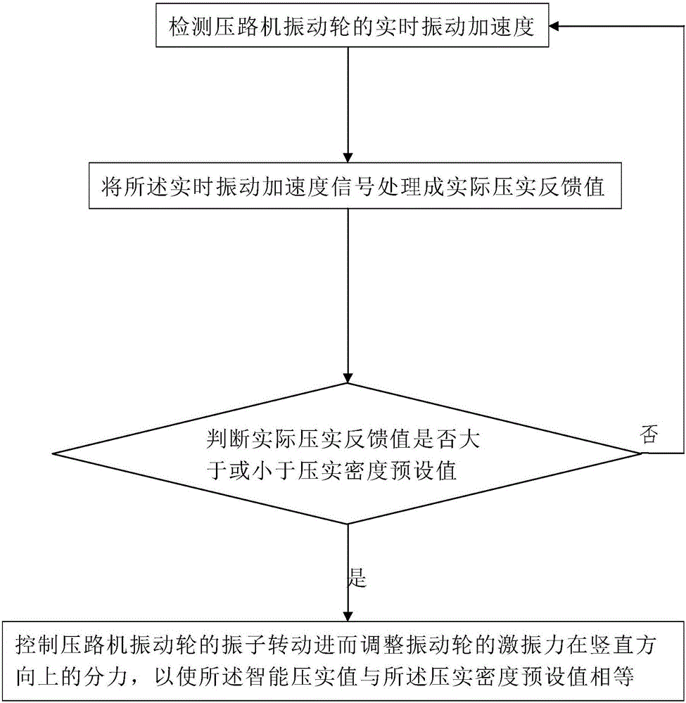
[0091] Such as figure 1 The shown method for controlling the exciting force of an intelligent direction-adjusting vibratory roller includes the following steps:

[0092] Step 1: Detect the real-time vibration acceleration of the vibrating wheel of the roller;

[0093] Step 2: Processing the real-time vibration acceleration signal into an actual compaction feedback value;

[0094] In this embodiment, in step 2, the specific method for processing the vibration acceleration signal into an actual compaction feedback value includes the following steps:

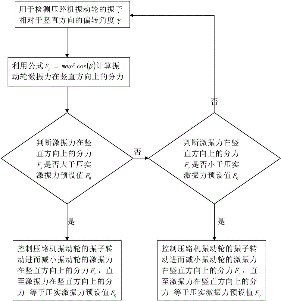
[0095] Step 201: Pass the formula g y (n)=g 1 cos(α)+g 2 cos(α) calculates two vibration acceleration signals g 1 And g 2 Value in the vertical direction, where g y (n) is the acceleration value in the vertical direction, α is the angle between the acceleration sensor used to detect the real-time acceleration signal and the vertical direction, in this embodiment, α=45°;

[0096] Step 202, to g y (n) Perform Fourier transform to obtain an arr...


PUM


Abstract

The invention discloses an excitation force control method of an intelligent steering vibratory roller. The method comprises the following steps: detecting the real-time vibration acceleration of a vibration wheel of the roller; processing a real-time vibration acceleration signal into an actual compaction feedback value; comparing the actual compaction feedback value with a preset compaction density value so as to judge whether the actual compaction feedback value is greater or less than the preset compaction density value or not; if yes, controlling a vibrator of the vibration wheel of the roller to rotate so as to adjust the component force, along the vertical direction, of the excitation force of the vibration wheel and further enable the actual compaction feedback value to be equal to the preset compaction density value. The invention also discloses an excitation force control system, comprising a first control subsystem formed by an acceleration sensor, a data processor and a central controller. The control system and the control method are capable of controlling the excitation force in real time, and enable the excitation force direction to change steplessly within a range of 0-90 degrees, thus steplessly adjusting the component force, along the vertical direction, of the excitation force from zero to maximum.

Description

Technical field [0001] The invention belongs to the technical field of vibratory roller control, and specifically relates to an exciting force control system and a control method of an intelligent direction-adjusting vibratory roller. Background technique [0002] Rotary vibrating roller. The rotary vibratory roller control system controls the vibration frequency of the roller by controlling the displacement of the vibrating hydraulic pump of the roller to realize the change of the exciting force of the roller. Its advantages are: simple structure, easy use, convenient maintenance, and simple electrical control system. The disadvantages are: low compaction efficiency, non-adjustable excitation force or small adjustment range, so real-time monitoring cannot be achieved. [0003] Vertical vibrating roller. The vertical vibratory roller control box system still controls the displacement of the vibratory hydraulic pump of the roller to control the frequency of the roller to realize ...

Claims


Application Information

Patent Timeline
IPC IPC(8): E01C19/28
CPCE01C19/28
Inventor 綦开隆王福堂
Owner SHAANXI JOINTARK MASCH GRP CO LTD
Why Eureka
Try Eureka