
Flexible connection ring anti-cracking anti-seepage and explosion-proof wall

A flexible connection, explosion-proof wall technology, applied in the direction of walls, building components, buildings, etc., can solve the fire resistance limit of the explosion-proof wall, the fire resistance level of the explosion-proof wall can not be dealt with, dangerous and other problems, achieve light weight, absorb explosion The effect of high impact energy and deformability

Inactive Publication Date: 2017-05-17
SHENYANG JIANZHU UNIVERSITY
View PDF0 Cites 3 Cited by
  • Summary
  • Abstract
  • Description
  • Claims
  • Application Information

AI Technical Summary

Problems solved by technology

However, there are also certain problems in the field of explosion-proof walls at present. Because the level of explosion is not certain, there are also certain problems in whether the fire resistance and explosion-resistant level of the main components of the explosion-proof wall can cope with the occurrence of various dangers. Explosion-proof The fire resistance limit of each component in the wall may not all meet the requirements, and there are also some problems in the anti-blast limit

Method used


Image

  • Flexible connection ring anti-cracking anti-seepage and explosion-proof wall
  • Flexible connection ring anti-cracking anti-seepage and explosion-proof wall
  • Flexible connection ring anti-cracking anti-seepage and explosion-proof wall

Examples


Embodiment Construction

[0015] In order to further illustrate the present invention, the present invention will be described in detail below in conjunction with the accompanying drawings and embodiments, but they should not be construed as limiting the protection scope of the present invention.

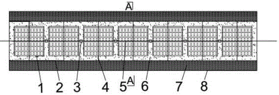
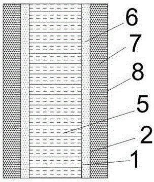
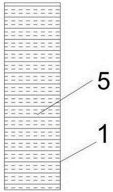
[0016] With reference to the accompanying drawings, a flexible connecting ring anti-crack and anti-seepage explosion-proof wall includes a rectangular explosion-proof steel plate 1, an explosion-proof and flame-retardant buffer steel plate 2, a flexible connection ring 3, an explosion-proof and flame-retardant buffer steel plate connector 4, and an internal light-weight energy-consuming and crack-resistant Damping material 5, high-toughness crack-resistant damping material 6, high-elastic flame-retardant buffer plate 7 and high-strength crack-resistant, seepage-proof and explosion-proof shell 8; The center line is the axis, and the inner and outer sides of the center line are symmetrically provided with recta...


PUM


Abstract

The invention discloses a flexible connection ring anti-cracking anti-seepage and explosion-proof wall. The outermost layer of a wall body is wrapped by a high-strength anti-cracking anti-seepage and explosion-proof shell body. Rectangular explosion-proof steel plates are symmetrically arranged on both sides of an inner center line, and the two sides of the rectangular explosion-proof steel plates are connected through flexible connection rings at the center line; the edges and the edges of the rectangular explosion-proof steel plates are opposite to form a quasi-rectangular cavity, and internal light energy dissipation and anti-cracking damping materials are poured inside the cavity; explosion-proof and flame retardant buffer steel plates are arranged on the inner side and the outer side of the rectangular explosion-proof steel plates correspondingly; and the explosion-proof and flame retardant buffer steel plates on the two sides of the rectangular explosion-proof steel plates are connected through explosion-proof and flame retardant buffer steel plate connecting pieces. Inside the wall body, high toughness and anti-cracking damping materials are poured between the rectangular explosion-proof steel plates and the explosion-proof flame retardant buffer steel plates, the damping materials are large in deformation ability and high in crack resistance ability, so that the energy generated by explosion shock to the utmost extent can be absorbed. Outside the wall body, high elastic and flame-retardant buffer plates are mounted between the two explosion-proof and flame retardant buffer steel plates and the outermost layer high-strength anti-cracking anti-seepage and explosion-proof shell body, so that the effects of flame-retardant and buffering are effectively achieved.

Description

technical field [0001] The invention relates to the field of structural engineering protective devices for preventing or reducing impact and guaranteeing damage to structures, in particular to a flexible connection ring anti-crack, anti-seepage and explosion-proof wall. Background technique [0002] Warehouses, shooting ranges, dormitories, ammunition depots, command posts, garages, hangars, oil depots, equipment rooms, temporary warehouses, bomb disposal stations, field hospitals, checkpoints and other military fortifications, as well as various flammable and explosive petrochemical products , often caused huge casualties and economic losses due to explosions. In order to control the losses caused by fires and explosions to the greatest extent, military safety explosion-proof walls, three-dimensional fortification explosion-proof walls, training base explosion-proof walls, field material warehouse explosion-proof walls, and field camps were built. Explosion-proof walls, exp...

Claims


Application Information

Patent Timeline
Patent Type & Authority Applications(China)
IPC IPC(8): E04B2/00E04B1/92
CPCE04B2/00E04B1/92
Inventor 张延年杨森
Owner SHENYANG JIANZHU UNIVERSITY
Learn More