
Roofing parapet water-floating structure and construction method thereof

A construction method and parapet technology, applied to roofs, roof coverings, building roofs, etc., can solve the problems of flexible sealing materials that are prone to aging and cracking, long production and installation cycles, and affect the appearance, so as to improve the quality of roof perception and waterproof Effect, good social benefit and economic benefit, cost reduction effect

Inactive Publication Date: 2017-05-17
HEBEI HENGSHAN CONSTR GRP CO LTD
View PDF9 Cites 19 Cited by
  • Summary
  • Abstract
  • Description
  • Claims
  • Application Information

AI Technical Summary

Benefits of technology

This technology prevents rainwater or other liquids from entering through gaps between layers inside an architectural feature called a sparer's hood (a type of shelf). It also helps maintain its structurally soundness while being durable against damage caused by environmental factors such as snow loadings. Additionally, it makes sure there are no cracks where liquid could leak out when subjected to impact forces like collisions with vehicles. Overall, this design enhances the overall appearance of buildings without compromising their safety measures.

Problems solved by technology

This patented technical problem addressed in this patents relates to improving the durability and reliance of water proof closures made from conventional materials such as steel rods embedded within concrete walls during building constructions due to their potential environmental issues caused by moisture intrusion into these components overtime.

Method used


Image

  • Roofing parapet water-floating structure and construction method thereof
  • Roofing parapet water-floating structure and construction method thereof
  • Roofing parapet water-floating structure and construction method thereof

Examples


Embodiment Construction

[0037] In order to make the object, technical solution and advantages of the present invention more clear, the present invention will be further described in detail below in conjunction with the accompanying drawings and specific embodiments. It should be understood that the specific embodiments described here are only used to explain the present invention, not to limit the present invention.

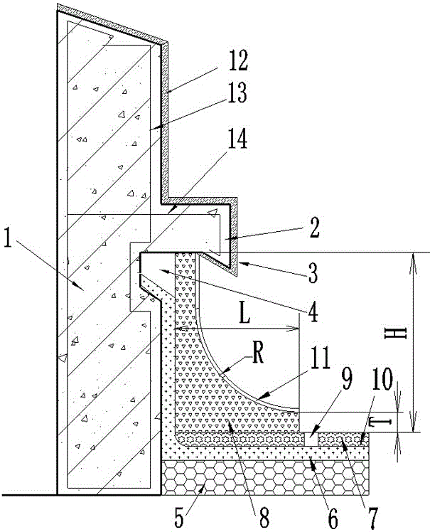
[0038] A kind of roof parapet flooding structure provided by the invention, such asfigure 1 As shown, it includes the overhanging eaves 2 that are horizontally arranged on the inner side wall of the parapet wall 1 and integrated with the parapet 1. The parapet 1 wall below the eaves 2 is provided with a press felt groove 4, and the leveling layer 6 is painted on the facade of the parapet 1 below the overhanging eaves 2 and the insulation layer 5 of the roof of the parapet 1 root. A waterproof layer 10 is laid above the layer 6, and the upper end of the waterproof layer 10 is placed in t...


PUM

PropertyMeasurementUnit
Densityaaaaaaaaaa

Abstract

The invention discloses a roofing parapet water-floating structure and a construction method thereof and relates to the technical field of parapet waterproof construction. A negative curved reinforcement is used for being bound with a longitudinal rebar in a parapet, and after a formwork is mounted, an overhanging eave in the inner side of the parapet and an olecranon convex eave at the lower end of the overhanging eave are formed through integrated pouring. A press felt groove is formed in the wall surface below. A screed-coat is smeared on a roofing heat preservation layer and the vertical face, below the overhanging eave, of the parapet. A waterproof layer is laid above the screed-coat, and a half header at the upper end of the waterproof layer is arranged in the press felt groove. A protecting layer is laid on the horizontal face of the screed-coat, a special-shaped extruded plate is pasted below the overhanging eave, the upper end of the special-shaped extruded plate is tightly attached to the overhanging eave, the vertical face of the special-shaped extruded plate is tightly attached to the portion, on the parapet, of the screed-coat, and the lower end of the special-shaped extruded plate is tightly attached to the protecting layer. A partition joint filled with gland packing is formed in the protecting layer on the outer side of the special-shaped extruded plate, and the special-shaped extruded plate is externally bonded with an anti-crack layer. Through the overhanging eave and the olecranon convex eave which are built during construction of the parapet, rainwater can be prevented from seeping from the half header of the protecting layer, the water-floating structure at the root of the parapet is protected against collision and treading, and integrality and rigidity of a decorating layer are improved.

Description


Claims


Application Information

Patent Timeline
Owner HEBEI HENGSHAN CONSTR GRP CO LTD
Learn More