Aeroengine

A technology for aero-engines and compressors, which is applied in the directions of machines/engines, mechanical equipment, gas turbines, etc., can solve the problems of low thrust efficiency and low pressure, and achieve the effect of high thrust efficiency and simple structure.

Inactive Publication Date: 2017-05-17
SHANGLING CO LTD
View PDF6 Cites 2 Cited by
  • Summary
  • Abstract
  • Description
  • Claims
  • Application Information

AI Technical Summary

Problems solved by technology

[0002] Although traditional aero-engines (especially military engines) have a technical solution for the afterburner

Method used


Image

  • Aeroengine
  • Aeroengine

Examples


Embodiment 1

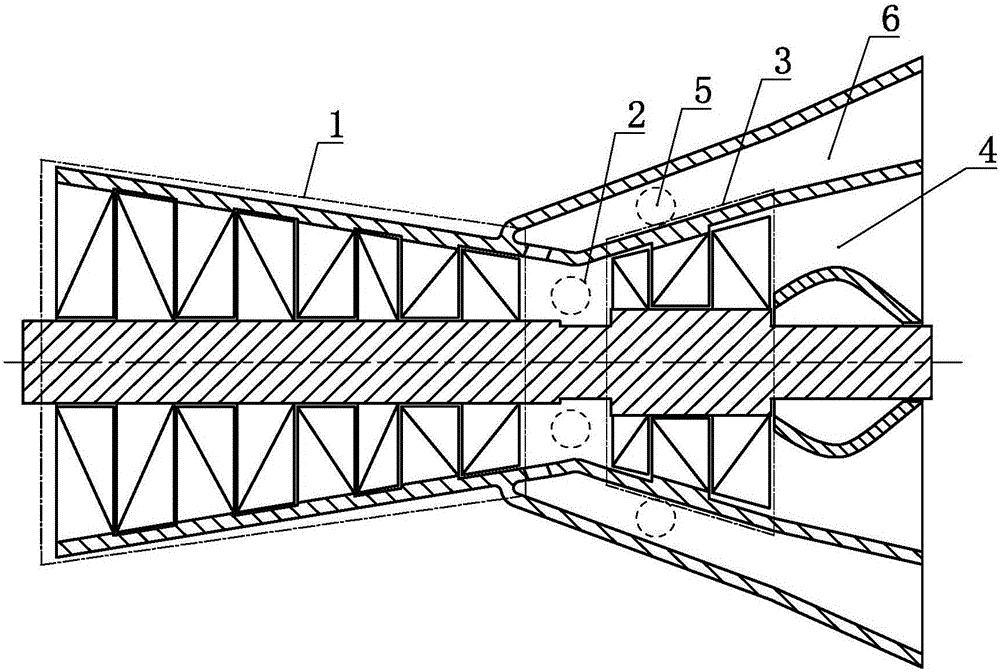
[0016] an aeroengine such as figure 1 As shown, it includes a compressor 1, a combustion chamber 2, a turbine 3, a nozzle 4, an auxiliary combustion chamber 5 and an auxiliary nozzle 6, and the compressor 1 communicates with the turbine 3 through the combustion chamber 2, and the The outlet of the working medium of the turbine 3 communicates with the nozzle 4, and a working medium outlet is provided on the fluid passage between the compressor 1 and the turbine 3, and the outlet of the working fluid passes through the auxiliary The combustion chamber 5 communicates with the auxiliary nozzle 6 .

[0017] As an alternative embodiment, in Embodiment 1 of the present invention, the auxiliary combustion chamber 5 and the combustion chamber 2 may be further selectively set to be set or not set together.

Embodiment 2

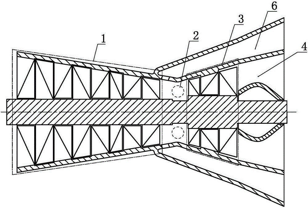
[0019] an aeroengine such as figure 2 As shown, it includes a compressor 1, a combustion chamber 2, a turbine 3, a nozzle 4 and an auxiliary nozzle 6, the compressor 1 communicates with the turbine 3 through the combustion chamber 2, and the turbine 3 The working medium outlet communicates with the nozzle 4 , and the combustion chamber 2 is provided with a working medium outlet, and the working medium outlet communicates with the auxiliary nozzle 6 .

[0020] As a changeable embodiment, Embodiment 1 and Embodiment 2 of the present invention and their changeable embodiments can further selectively choose to make the nozzle pipe 4 and the auxiliary nozzle pipe 6 fit or not.


PUM


Abstract

The invention discloses an aeroengine. The aeroengine comprises a gas compressor, a combustion chamber, a turbine, a nozzle pipe, an auxiliary combustion chamber and an auxiliary nozzle pipe, wherein the gas compressor communicates with the turbine through the combustion chamber; a working medium outlet of the turbine communicates with the nozzle pipe; a working medium leading-out opening is formed in a fluid channel between the gas compressor and the turbine; and the working medium leading-out opening communicates with the auxiliary nozzle pipe through the auxiliary combustion chamber. The aeroengine disclosed by the invention is simple in structure and high in thrust efficiency.

Description

technical field [0001] The invention relates to the field of thermal energy and power, in particular to an aero engine. Background technique [0002] Although traditional aero-engines (especially military engines) have the technical scheme of the afterburner, the afterburner is arranged after the turbine, so the pressure is relatively low, and the thrust efficiency must be low. Therefore, need to invent a kind of new aero-engine. Contents of the invention [0003] In order to solve the above problems, the technical scheme proposed by the present invention is as follows: [0004] An aero-engine of the present invention comprises a compressor, a combustion chamber, a turbine, a nozzle, an auxiliary combustion chamber and an auxiliary nozzle, the compressor communicates with the turbine through the combustion chamber, and the turbine The outlet of the working fluid communicates with the nozzle, and a working fluid outlet is provided on the fluid channel between the compress...

Claims


Application Information

Patent Timeline
IPC IPC(8): F02C3/04F02C3/14F02K1/00
CPCF02C3/04F02C3/14F02K1/00
Inventor 靳北彪
Owner SHANGLING CO LTD
Why Eureka
Try Eureka