Supercharge Your Innovation With Domain-Expert AI Agents!

Centrifugal blower

A blower, centrifugal technology, applied in the field of centrifugal blowers, can solve problems such as increased noise, air disturbance, and reduced air blowing effectiveness

Active Publication Date: 2017-05-17
DENSO CORP
View PDF5 Cites 6 Cited by
  • Summary
  • Abstract
  • Description
  • Claims
  • Application Information

AI Technical Summary

Problems solved by technology

As a result, the air flowing from the surface of the intake annulus into the vicinity of the side plates of the impeller may be disturbed
As the turbulence moves downstream, the turbulence generated near the side plates of the impeller may become stronger, whereby noise may increase and blowing effectiveness may decrease

Method used


Image

  • Centrifugal blower
  • Centrifugal blower
  • Centrifugal blower

Examples


no. 1 example

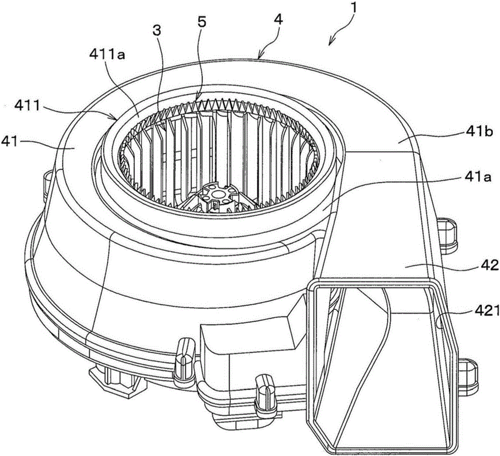
[0032] The centrifugal blower 1 according to the first embodiment will refer to Figure 1 to Figure 8 Explained below. figure 1 The centrifugal blower 1 of the present embodiment shown is used in an air blowing unit that blows air to an interior unit such as an air conditioner for a vehicle.

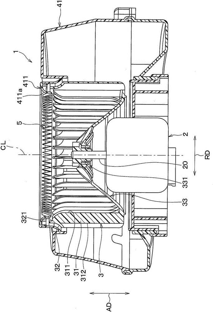
[0033] Such as figure 2 As shown, the centrifugal blower 1 includes: a motor 2 having a rotating shaft 20 ; an impeller 3 driven and rotated by the motor 2 to blow air; and a case 4 accommodating the impeller 3 . figure 2 Arrows AD shown indicate the axial direction of the rotary shaft 20 . figure 2 Arrow RD shown indicates a radial direction perpendicular to the axial direction AD of the rotary shaft 20 .

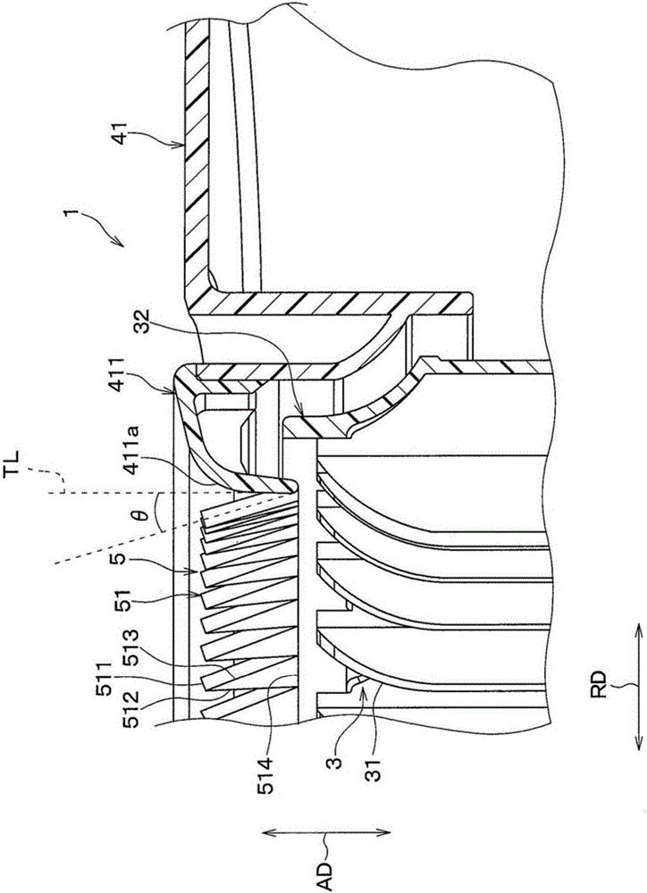
[0034] The impeller 3 is a component that rotates around the axis CL of the rotary shaft 20, and the impeller 3 has a cylindrical shape. The impeller 3 includes: a plurality of blades 31 radially arranged around the rotating shaft 20; a side plate 32 having a ring shape and on...

no. 2 example

[0064] Next, refer to Figure 10-13 A second embodiment of the present disclosure is explained below. The present embodiment differs from the first embodiment in that the vertical vortex generating portion 5 is formed of a plurality of protruding portions 52 having a three-sided pyramid shape.

[0065] Such as Figure 10 and 11 As shown, the centrifugal blower 1 of the present embodiment includes a vertical vortex generating portion 5 formed of a plurality of protruding portions 52 arranged on the entire circumference of a rim portion 411 a of an air intake portion 411 . Such as Figure 12 As shown, the vertical vortex generating portion 5 of the present embodiment is formed by a protruding portion 52 having a three-sided pyramid shape inwardly from the edge portion 411a of the intake portion 411 in the radial direction of the rotating shaft 20 protrude.

[0066] Each raised portion 52 comprises two sides 522, 523 in a downstream surface 521 positioned downstream of the a...

no. 3 example

[0073] Next, refer to Figure 14 and 15 A third embodiment is explained below. The present embodiment differs from the first embodiment in that even the deflecting portion where the airflow along the edge portion 411 a of the intake portion 411 is deflected toward the side plate 32 is formed by the plasma actuator 6 .

[0074] The plasma actuator 6 is an actuator that generates induced air flow toward the side plate of the impeller 3 by generating plasma in the rim portion 411 a of the intake portion 411 .

[0075] The plasma actuator 6 comprises a device 61 having a non-conductive body 611, a first side electrode 612 disposed on a first side of the non-conductive body 611, and a second side electrode 612 disposed on a second side of the non-conductive body 611. Electrode 613. The second side may be the opposite side of the first side. The plasma actuator 6 further includes an AC supply portion 62 supplying an AC voltage between the first side electrode 612 and the second ...


PUM


Abstract

A centrifugal blower includes a rotation shaft, an impeller, a casing, and a deflection portion. The impeller rotates about the rotation shaft to draw an air therein in an axial direction of the rotation shaft and discharge the air outward in a radial direction of the rotation shaft. The impeller includes a plurality of blades and a side panel having an annular shape and connecting the plurality of blades in the axial direction. The casing accommodates the impeller and includes an air intake portion adjacent to the side panel. The air intake portion has a bell mouth shape to have a rim portion that defines an opening through which the drawn air is guided to an inside of the impeller. The deflection portion deflects an airflow along the rim portion of the air intake portion toward the side panel.

Description

technical field [0001] The present disclosure relates to a centrifugal blower. Background technique [0002] Generally, a centrifugal blower is well known, which sucks inside air from one side in the axial direction of the rotating shaft and discharges the air outward in the radial direction of the rotating shaft. [0003] Patent Document 1 (JP H8-247090) discloses blowing characteristics of a centrifugal blower and a configuration for reducing noise. Patent Document 1 discloses a configuration in which small protrusions are arranged concentrically with the intake ring on the surface of the inflow portion of the intake ring inserted into the intake portion of the impeller. The height of the small protrusions is less than the boundary layer thickness of the laminar flow. [0004] According to the configuration disclosed in Patent Document 1, since the speed difference between the air flow along the intake ring and the main flow away from the surface of the intake ring is sm...

Claims


Application Information

Patent Timeline
Patent Type & Authority Applications(China)
IPC IPC(8): F04D29/28F04D29/42F04D29/44F04D29/66
CPCF04D29/283F04D29/4213F04D29/441F04D29/661F04D29/162F04D29/4226F04D29/681F04D17/16F04D29/282F04D29/687
Inventor 小坂翔小田修三
Owner DENSO CORP
Features
  • R&D
  • Intellectual Property
  • Life Sciences
  • Materials
  • Tech Scout
  • Unparalleled Data Quality
  • Higher Quality Content
  • 60% Fewer Hallucinations
Learn More