Supercharge Your Innovation With Domain-Expert AI Agents!

Rotating type bottle holder structure and refrigerator

A rotary, bottle holder technology, used in lighting and heating equipment, cooling fluid circulation devices, household appliances, etc., can solve the problems of fixed bottle holders, reduced available space, and occupation of internal space of the box.

Inactive Publication Date: 2017-05-17
HEFEI HUALING CO LTD +2
View PDF8 Cites 4 Cited by
  • Summary
  • Abstract
  • Description
  • Claims
  • Application Information

AI Technical Summary

Problems solved by technology

[0004] The purpose of the present invention is to provide a rotary bottle holder structure and refrigerator, to solve the problem that the bottle holder in the prior art is fixed after being installed on the door body, thus resulting in the inability to place taller items and closing the door. The back of the body will occupy a large space inside the box, so that the available space inside the box becomes smaller, resulting in the technical problem that many items cannot be stored

Method used


Image

  • Rotating type bottle holder structure and refrigerator
  • Rotating type bottle holder structure and refrigerator
  • Rotating type bottle holder structure and refrigerator

Examples


Embodiment 1

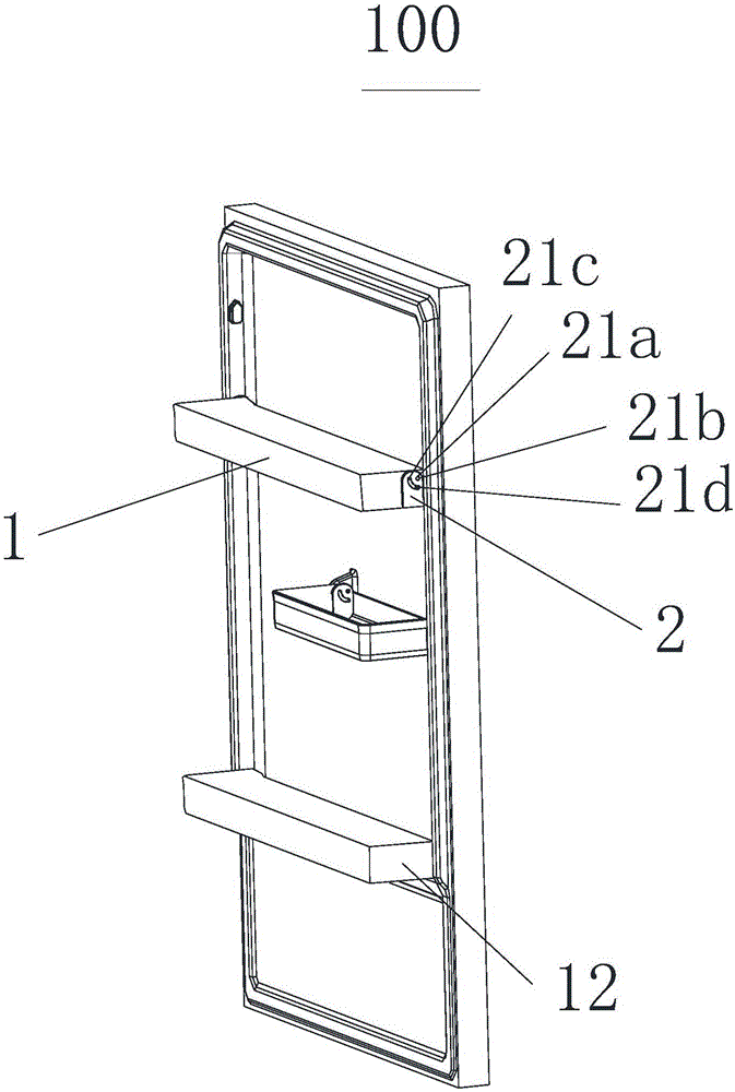
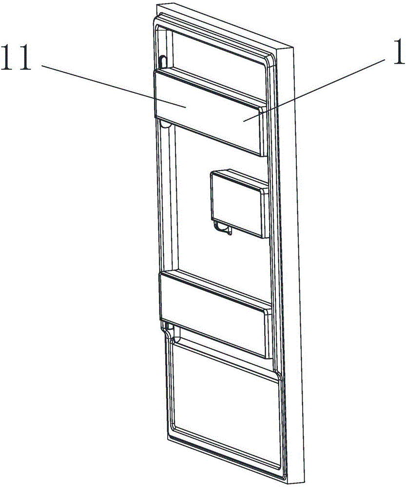
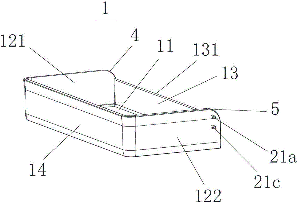
[0032] Embodiment 1: a fixed rotating shaft 21a and a sliding rotating shaft 21c are arranged on the outer surface of the side plate 12 adjacent to the end of the rear side plate 13 at the left and right ends of the bottom plate 11. The fixed rotating shaft hole 21b and the rotating groove 21d are spaced apart. The fixed rotating shaft 21a is rotatably fitted in the fixed rotating shaft hole 21b, and the sliding rotating shaft 21c is slidably fitted in the rotating groove 21d. The rotating shaft 21a rotates in the fixed rotating shaft hole 21b and makes the sliding rotating shaft 21c reciprocally slide in the rotating groove 21d. When the sliding rotating shaft 21c matches the engaging part 3, the rotary bottle holder 1 changes from the original horizontal position to the vertical position. straight position. It should be noted that the above-mentioned fixed rotating shaft 21 a and sliding rotating shaft 21 c are provided on the left side board 121 and the right side board 122...

Embodiment 2

[0033]Embodiment 2: On the outer surface of the side plate 12 at the left and right ends of the base plate 11, adjacent to the end of the rear side plate 13, spaced apart fixed shaft holes 21b and rotation grooves 21d are provided. A fixed shaft 21a and a sliding shaft 21c are respectively constructed on the top, wherein the fixed shaft 21a is rotatably fitted in the fixed shaft hole 21b, and the sliding shaft 21c is slidably fitted in the rotating groove 21d, and the rotating bottle holder 1 is fixed to The rotating shaft 21a rotates in the fixed rotating shaft hole 21b and makes the sliding rotating shaft 21c reciprocally slide in the rotating groove 21d. When the sliding rotating shaft 21c matches the engaging part 3, the rotary bottle holder 1 changes from the original horizontal position to the vertical position. straight position. It should be noted that the above-mentioned fixed shaft hole 21 b and the rotation groove 21 d are provided on the left side plate 121 and the...

Embodiment 3

[0034] Embodiment 3: On the outer surface of the end of the side plate 12 adjacent to the rear side plate 13 at the left and right ends of the bottom plate 11, spaced apart fixed rotating shafts 21a and rotating grooves 21d are provided. On the bottle holder fixed plate 2 A fixed shaft hole 21b and a sliding shaft 21c are respectively configured, wherein the fixed shaft 21a is rotatably fitted in the fixed shaft hole 21b, and the sliding shaft 21c is slidably fitted in the rotating groove 21d, and the rotating bottle holder 1 is fixed so as to The rotating shaft 21a rotates in the fixed rotating shaft hole 21b and makes the sliding rotating shaft 21c reciprocally slide in the rotating groove 21d. When the sliding rotating shaft 21c matches the engaging part 3, the rotary bottle holder 1 changes from the original horizontal position to the vertical position. straight position. It should be noted that the above-mentioned fixed rotating shaft 21 a and rotating groove 21 d are pro...


PUM


Abstract

The invention relates to the technical field of refrigeration equipment and discloses a rotating type bottle holder structure and a refrigerator. The rotating type bottle holder structure comprises a rotating type bottle holder and a bottle holder fixing plate, the rotating type bottle holder comprises a base plate and side plates, and the side plates are arranged at the left end and the right end of the base plate correspondingly. A fixing rotating shaft is arranged on one of the bottle holder fixing plate and each side plate, a fixing rotating shaft hole is formed in the other one of the bottle holder fixing plate and each side plate, and each fixing rotating shaft is rotatably arranged in the corresponding fixing rotating shaft hole in a matched mode. A sliding rotating shaft is arranged on one of the bottle holder fixing plate and each side plate, a rotating groove is formed in the other one of the bottle holder fixing plate and each side plate, a clamping portion is structured on the groove wall of the locking end of each rotating groove, and each sliding rotating shaft is slidingly arranged in the corresponding rotating groove in a matched mode. By rotating the rotating type bottle holder, the fixing rotating shafts rotate in the fixing rotating shaft holes to enable the sliding rotating shafts to slide in a reciprocating mode in the rotating grooves, and the rotating type bottle holder changes from an original horizontal position to a vertical position when the sliding rotating shafts are matched with the clamping portions. The rotating type bottle holder structure has the advantage of saving the inner space of the refrigerator.

Description

technical field [0001] The invention relates to the technical field of refrigeration equipment, in particular to a rotary bottle holder structure and a refrigerator. Background technique [0002] In the prior art, the door of the refrigerator is provided with a bottle holder for containing items, but there are the following problems. Usually, the bottle holder is fixed after being installed on the door body. Due to the limitation of the distance between the two bottle holders, When a taller item is placed on the lower bottle holder, it will interfere with the upper bottle holder, resulting in the inability to place taller items. On the other hand, after closing the door body, because the bottle holder on the door body will occupy a large space inside the box body, the available space inside the box body becomes smaller, resulting in the inability to store many items. Contents of the invention [0003] (1) Technical problems to be solved [0004] The purpose of the presen...

Claims


Application Information

Patent Timeline
IPC IPC(8): F25D23/04
CPCF25D23/04F25D23/028F25D2323/02
Inventor 陈明益耿秀华陈浩
Owner HEFEI HUALING CO LTD
Features
  • R&D
  • Intellectual Property
  • Life Sciences
  • Materials
  • Tech Scout
  • Unparalleled Data Quality
  • Higher Quality Content
  • 60% Fewer Hallucinations
Learn More