A rotary kiln temperature measuring device
A technology of temperature measuring device and rotary kiln, applied in the direction of rotary drum furnace, furnace, furnace type, etc., can solve the problems of temperature measuring shaft wear and tear, large error, constant change, etc., to reduce impact, reduce maintenance times, and prolong service life The effect of longevity
- Summary
- Abstract
- Description
- Claims
- Application Information
AI Technical Summary
Problems solved by technology
Method used
Image
Examples
Embodiment 1
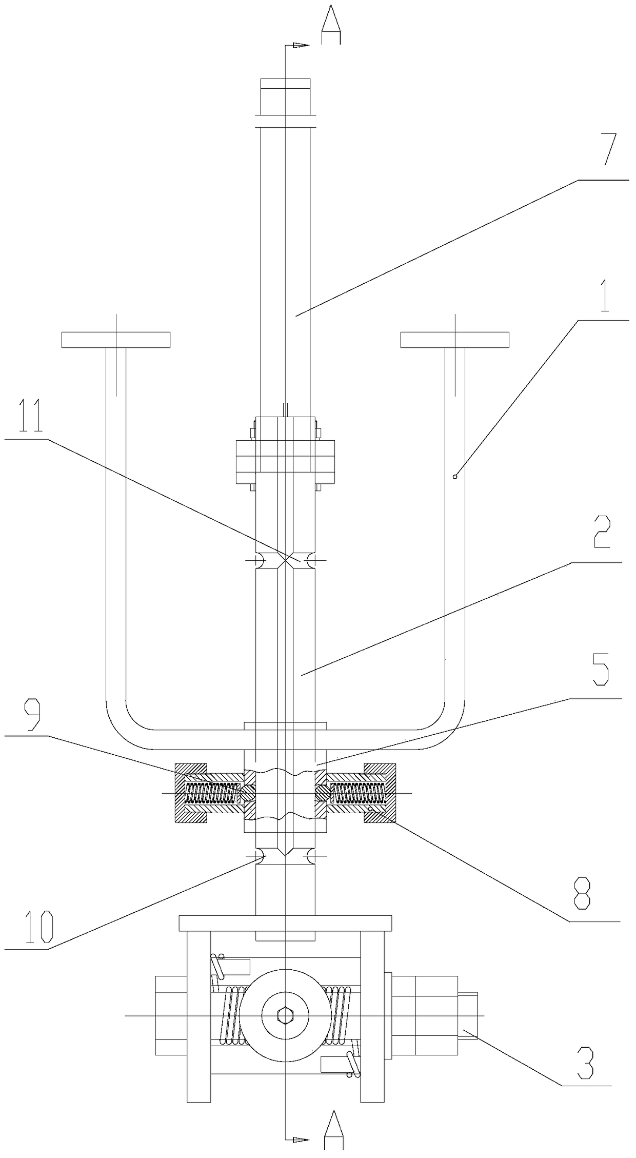
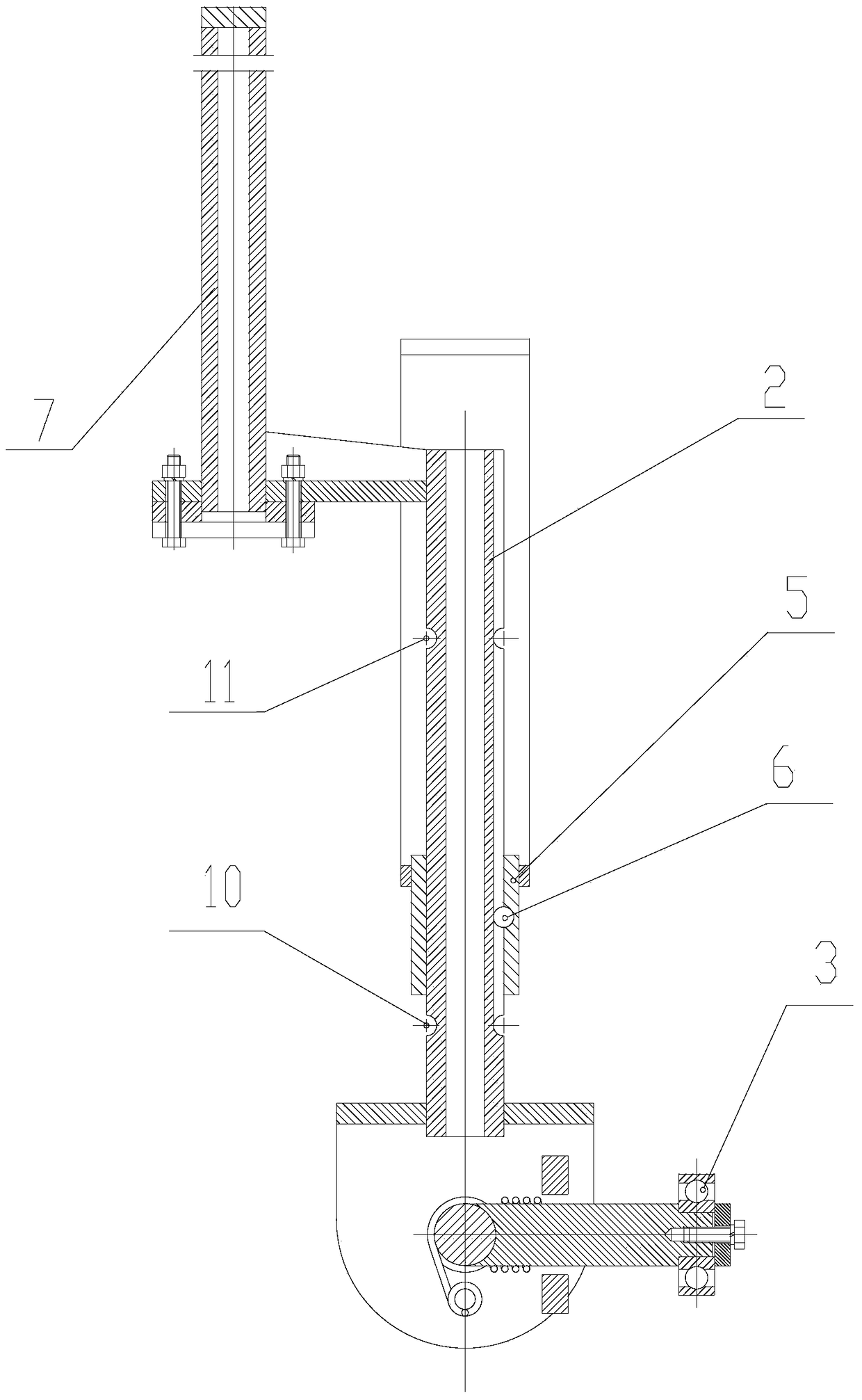
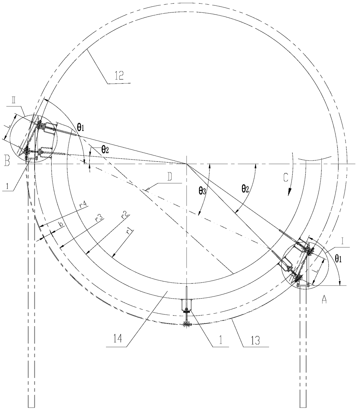
[0029] The rotary kiln temperature measuring device of the present embodiment 1 includes a mounting bracket 1, a sliding column 2, a temperature measuring shaft (not shown in the figure), a guide wheel 3 and a positioning piece, please refer to figure 1 and figure 2 . Specifically, the installation bracket 1 is fixed on the side wall of the rotary kiln 14 , and a temperature measuring through hole is opened on the side wall of the rotary kiln 14 corresponding to the position of the installation bracket 1 . The sliding column 2 is installed on the installation bracket 1 , and the sliding column 2 can rotate with the rotary kiln 14 . The first end of the sliding column 2 is close to the temperature measuring through hole, and the temperature measuring shaft is fixed at the first end of the sliding column 2; the second end of the sliding column 2 is far away from the temperature measuring through hole. hole, and the second end of the sliding column 2 is equipped with a rail wh...
Embodiment 2
[0049] The difference between the second embodiment and the first embodiment lies in the difference of the limiting parts. In the second embodiment, in order to control the movement of the sliding column 2 along the axial direction of the temperature measuring through hole and realize the effect of periodic monitoring of the temperature in the rotary kiln 14, the positioning parts are arranged on the temperature measuring arc section 12 and The temperature-measuring guide rail and the non-temperature-measuring guide rail on the non-temperature-measuring arc section 13.
[0050] At this time, since no additional clamping spring 8 is provided to fix the temperature measuring shaft, the temperature measuring shaft will move along the axial direction of the temperature measuring through hole under the action of gravity. In order to avoid the uncontrolled movement of the temperature measuring shaft under the action of gravity, the temperature measuring guide rail, the non-temperatu...
PUM
 Abstract
Description
Claims
Application Information
 - R&D
- Intellectual Property
- Life Sciences
- Materials
- Tech Scout
- Unparalleled Data Quality
- Higher Quality Content
- 60% Fewer Hallucinations
Browse by: Latest US Patents, China's latest patents, Technical Efficacy Thesaurus, Application Domain, Technology Topic, Popular Technical Reports.
© 2025 PatSnap. All rights reserved.Legal|Privacy policy|Modern Slavery Act Transparency Statement|Sitemap|About US| Contact US: help@patsnap.com


