User interface display apparatus and panorama monitoring system for switch cabinet

A display device and user interface technology, applied in the field of high-voltage switchgear, can solve the problems of complicated maintenance and debugging process and high debugging cost

Active Publication Date: 2017-05-17
STATE GRID SHANDONG ELECTRIC POWER
View PDF7 Cites 5 Cited by
  • Summary
  • Abstract
  • Description
  • Claims
  • Application Information

AI Technical Summary

Problems solved by technology

[0005] In view of this, the object of the present invention is to provide a user interface display device and a switch cabinet panoramic monitoring system, so as to alleviate the technical problems of complicated maintenance and debugging process and high debugging cost in the prior art

Method used


Image

  • User interface display apparatus and panorama monitoring system for switch cabinet
  • User interface display apparatus and panorama monitoring system for switch cabinet
  • User interface display apparatus and panorama monitoring system for switch cabinet

Examples


Embodiment 1

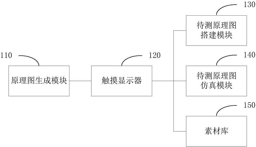
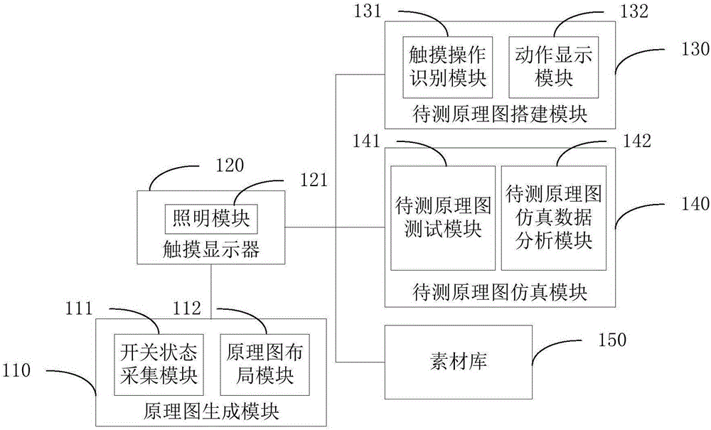
[0051] see figure 1 , is a schematic structural diagram of a user interface display device provided by an embodiment of the present invention. The user interface display device 100 provided by the embodiment of the present invention includes a schematic diagram generation module 110 , a touch display 120 , a schematic diagram construction module 130 to be tested and a schematic diagram simulation module 140 to be tested.

[0052] The schematic diagram generating module, the schematic diagram building module to be tested and the schematic diagram simulation module to be tested are respectively connected with the touch display. Specifically, the output terminal of the schematic diagram generating module is connected to the input terminal of the touch display, and the generated schematic diagram is transmitted to the touch display. The construction module of the schematic diagram to be tested and the simulation module of the schematic diagram to be tested are respectively bidire...

Embodiment 2

[0067] like Figure 4 As shown, a schematic structural diagram of a switch cabinet panoramic monitoring system provided by an embodiment of the present invention. The embodiment of the present invention also provides a switchgear panorama monitoring system, including an environmental temperature and humidity monitoring device 200 , an isolating switch monitoring device 300 , a vacuum monitoring device 400 , an insulation monitoring device 500 and the above-mentioned user interface display device 100 .


PUM


Abstract

The invention provides a user interface display apparatus and a panorama monitoring system for a switch cabinet, and relates to the technical field of a high voltage switch cabinet. The panorama monitoring system for a switch cabinet includes an environment temperature and humidity measuring device, an isolation switch monitoring device, a vacuum monitoring device, an insulation monitoring device and a user interface display apparatus, and generates environment temperature and humidity data, switch motion information, switch motion images, vacuum monitoring data and insulator monitoring data, wherein the user interface display apparatus includes a schematic diagram generation module, a touch display, a schematic diagram to be measured establishing module and a schematic diagram to be measured simulation module; the schematic diagram generation module generates a schematic diagram; the schematic diagram to be measured establishing module establishes a schematic diagram to be measured according to a command of a user; the touch display displays the schematic diagram and the schematic diagram to be measured; and the schematic diagram to be measured simulation module performs a simulation test on the schematic diagram to be measured and outputs the result. The technical scheme of the user interface display apparatus and the panorama monitoring system for a switch cabinet solves the technical problem that the maintenance debugging process in the prior art is complicated and tedious, and realizes simplification of the maintenance debugging flow.

Description

technical field [0001] The invention relates to the technical field of high-voltage switch cabinets, in particular to a user interface display device and a switch cabinet panoramic monitoring system. Background technique [0002] Switching appliances play an important role in control and protection in power systems. With the continuous improvement of the automation level of the power system and the development of smart grid technology, the requirements for the reliability of the switchgear are getting higher and higher, and the switchgear is required to be compatible with the development of substation integrated automation and distribution automation. Intelligent switchgear is a new generation of switchgear developed by introducing computer technology, digital processing technology and network communication technology into traditional switchgear. Intelligentization has gradually become an important development direction of switching appliances. [0003] At present, there a...

Claims


Application Information

Patent Timeline
Patent Type & Authority Applications(China)
IPC IPC(8): G01D21/02G06F3/0488
Inventor 彭红霞刘相兴王智杰李永生贾斌
Owner STATE GRID SHANDONG ELECTRIC POWER
Why Eureka
Try Eureka