
Water test table for toilet bowls

A technology for a water test stand and a toilet is applied in the field of toilet flushing performance testing devices, which can solve the problems of insufficient water pressure and the inability of water to be smoothly drawn into the toilet.

Active Publication Date: 2017-05-17
JINJIANG YABANG GLASS FIBER REINFORCED PLASTIC
View PDF6 Cites 0 Cited by
  • Summary
  • Abstract
  • Description
  • Claims
  • Application Information

AI Technical Summary

Problems solved by technology

During the test, the toilet to be tested is placed on the platform-type flat water test bench, the outlet pipe of the water pump is connected to the water tank of the toilet to be tested, and the water pump is started to work. A plastic ball imitating the flushed material can be placed in the toilet, and the water pump will discharge the water in the reservoir. Pump the water into the water tank, press the toilet switch to flush the toilet, and the flushed water flows back into the reservoir through the drain port on the platform-type flat water test bench, so as to realize the recycling of test water. During the flushing test, the toilet The plastic balls inside will directly rush into the reservoir from the drain, so that the flushing effect of the toilet can be judged by observing the number of plastic balls in the reservoir; the water test bench still has the following deficiencies in actual use: 1. After the ball is flushed into the reservoir, it is necessary to open the platform-type flat water test table to pick up the plastic ball and reuse it; 2. If the water pressure in the reservoir is low, simply relying on the water pump to pump the water into the toilet may cause water leakage. Insufficient pressure, water cannot be smoothly pumped into the toilet

Method used


Image

  • Water test table for toilet bowls
  • Water test table for toilet bowls
  • Water test table for toilet bowls

Examples


Embodiment Construction

[0020] In the following, the present invention will be further described in conjunction with the accompanying drawings and specific embodiments, so as to understand more clearly the technical idea claimed in the present invention.

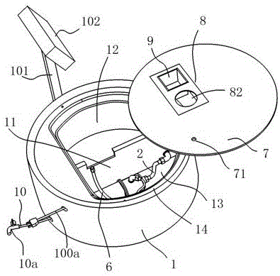
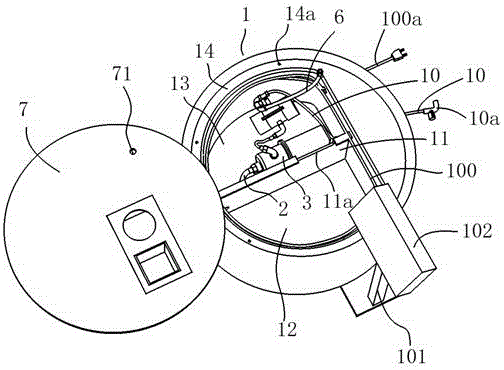
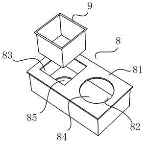
[0021] like Figure 1-4 Shown is a toilet water testing platform of the present invention, comprising a housing 1, a suction pipe 2, a water pump 3, a connecting pipe 4, a pressurized tank 5, a water inlet pipe 6, a support plate 7, a drainage box 8 and a basket 9, and the housing 1 The water storage chamber 12 and the pump chamber 13 are separated by the isolation plate 11. The upper opening of the housing 1 is provided with a support platform 14 along the inner edge. The water pump 3 is installed in the pump chamber 13, and one end of the suction pipe 2 is installed on the isolation plate. The bottom of 11 communicates with the water storage chamber 12, the other end of the suction pipe 2 is connected to the pump inlet of the water pump 3, the su...


PUM


Abstract

The invention discloses a water test table for toilet bowls. The water test table comprises a shell, a water drawing pipe, a water pump, a water inlet pipe, a support plate, a connecting pipe, a pressurizing tank, a drainage box and a basket. The connecting pipe is arranged between a pump outlet of the water pump and a water inlet end of the pressurizing tank in a connected manner, and a water outlet end of the pressurizing tank is connected with the water inlet pipe; the drainage box is arranged on the support plate and is positioned above a water storage chamber, a first drainage hole and a basket fixing hole are respectively formed in a top box wall of the drainage box, a second drainage hole is formed in a bottom box wall of the hollow drainage box and is formed in a position below the basket fixing hole, the basket is mounted on the basket fixing hole, the lower end of the basket is in contact with the bottom box wall of the drainage box, a support groove is formed in a partition plate of the shell and is formed in a position below the drainage box, and the lower end of the drainage box is fixedly supported on the support groove. The water test table has the advantages that the quantities of flushed plastic balls can be intuitively judged, and accordingly flushing effects of the toilet bowls can be judged; the plastic balls can be conveniently reused after being fetched, water can be smoothly drawn by the water pump, and the toilet bowls can be automatically filled with the water.

Description

technical field [0001] The invention relates to the technical field of a toilet flushing performance testing device, in particular to a toilet water testing platform. Background technique [0002] In order to facilitate testing the flushing effect of the toilet when purchasing the toilet, a Chinese utility model patent (notification number CN204898807) discloses a circulating water test bench for a glass fiber reinforced plastic toilet, which includes a housing, a reservoir, a pump chamber, a water pump and a platform plate The water test platform, the shell is made of glass fiber reinforced plastic into a circular straight barrel structure, the inner edge of the upper mouth of the shell is provided with a support platform, the bottom wall of the lower end of the shell and the surrounding side walls form a water reservoir, and the rear side of the shell is set There is a pump room isolated from the reservoir. The water pump is installed in the pump room. The inlet pipe of th...

Claims


Application Information

Patent Timeline
IPC IPC(8): G01M99/00E03D5/016E03D9/00E03D9/16
CPCG01M99/008E03D5/016E03D9/00E03D9/16
Inventor 洪长明
Owner JINJIANG YABANG GLASS FIBER REINFORCED PLASTIC
Learn More