Display panel and production method of LED and display
A technology of light-emitting diodes and display panels, applied in static indicators, optics, instruments, etc., can solve problems such as crosstalk, and achieve the effect of solving 3D crosstalk and improving the effect of 3D experience.
- Summary
- Abstract
- Description
- Claims
- Application Information
AI Technical Summary
Problems solved by technology
Method used
Image
Examples
Embodiment 1
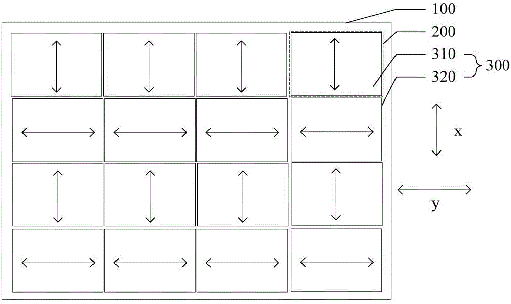
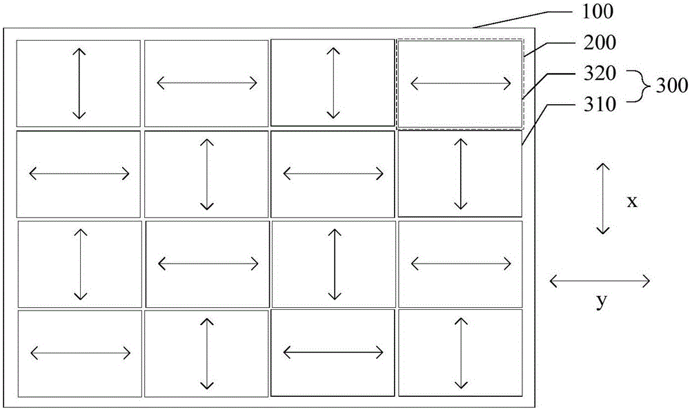
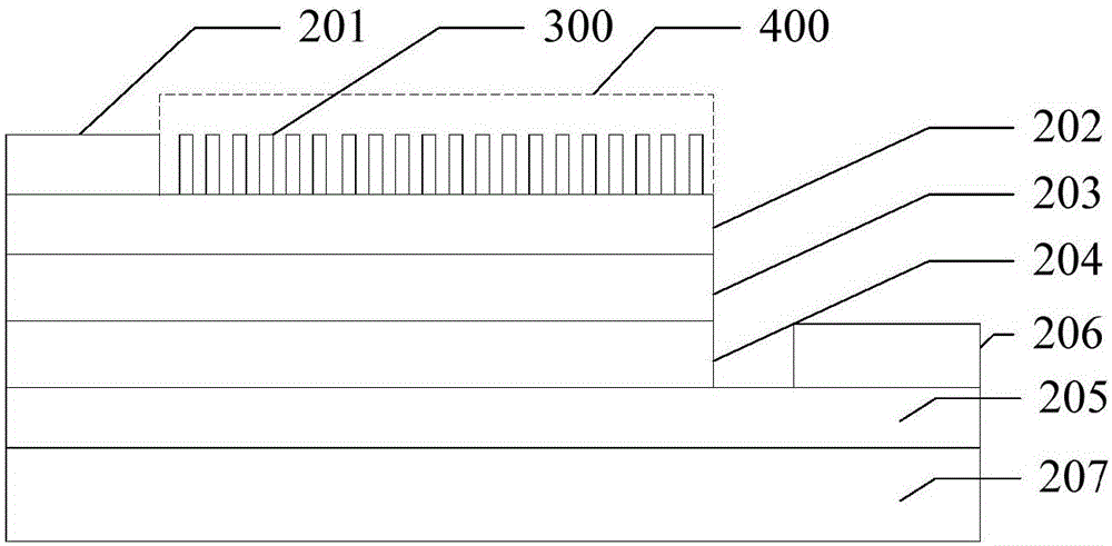
[0020] This embodiment provides a light emitting diode display panel, such as figure 1 As shown, the light-emitting diode display panel includes: a substrate 100, on which a plurality of light-emitting diodes 200 arranged in an array are arranged; The plurality of polarizing layers 300 are arranged in one-to-one correspondence, that is, one polarizing layer 300 is arranged on the light emitting side of each LED 200 . Such as figure 1 As shown, the light-emitting diode 200 is shown in the dashed box. In this embodiment, the light-emitting side of the light-emitting diode 200 is located on the side away from the substrate 100 as an example. The polarizing layer 300 is arranged on the light-emitting side of the light-emitting diode 200, that is, the polarizing layer 300 is arranged on The light-emitting diode 200 is away from the side of the substrate 100, but is not limited thereto. For example, the light-emitting side of the light-emitting diode 200 can also be located on the ...
Embodiment 2
[0045] The difference from the first embodiment is that the light emitting diode provided in this embodiment includes multiple light emitting diode groups, and each light emitting diode group includes at least two light emitting diodes of different colors, so a colorful 3D display effect can be realized.
[0046] Figure 4 A schematic diagram of a light-emitting diode display panel provided in this embodiment, such as Figure 4 As shown, the plurality of LEDs 200 includes a plurality of groups of LEDs, including groups 210 and 220 of LEDs, for example. The light emitting diode group 210 includes three light emitting diodes 211, 212 and 213 of different colors, the light emitting diode group 220 includes three light emitting diodes 221, 222 and 223 of different colors, and each light emitting diode in each light emitting diode group The polarizing directions of the polarizing layers 300 disposed on the light emitting side are the same. For example, if Figure 4 As shown, the...
Embodiment 3
[0050] This embodiment provides a method for manufacturing a light-emitting diode display panel, such as Figure 6 As shown, the manufacturing method of the light-emitting diode display panel includes: forming a plurality of light-emitting diodes arranged in an array on a substrate; One-to-one correspondence is provided, and the plurality of polarizing layers includes a plurality of first polarizing layers and a plurality of second polarizing layers with different polarization directions. The light-emitting diode display panel produced by the method for producing the light-emitting diode display panel can form different polarized display images row by row / column or one by one. image, so as to achieve monochrome or color 3D display effect. The light-emitting diode display panel produced by the method for producing the light-emitting diode display panel can solve problems such as 3D crosstalk, thereby improving the 3D experience effect.
[0051] For example, forming a light-em...
PUM
 Abstract
Description
Claims
Application Information
 - R&D
- Intellectual Property
- Life Sciences
- Materials
- Tech Scout
- Unparalleled Data Quality
- Higher Quality Content
- 60% Fewer Hallucinations
Browse by: Latest US Patents, China's latest patents, Technical Efficacy Thesaurus, Application Domain, Technology Topic, Popular Technical Reports.
© 2025 PatSnap. All rights reserved.Legal|Privacy policy|Modern Slavery Act Transparency Statement|Sitemap|About US| Contact US: help@patsnap.com


