Antenna structure and design method

An antenna structure and linear array technology, applied in the fields of electronics, radar, microwave and radio frequency, can solve the problems of circuit board area, cost increase, large feeding network area, and increase the complexity of the back-end algorithm, so as to achieve the feeding network area Reduce and expand the effect of application scenarios

Active Publication Date: 2017-05-17
SOUTHEAST UNIV +1
View PDF6 Cites 18 Cited by
  • Summary
  • Abstract
  • Description
  • Claims
  • Application Information

AI Technical Summary

Problems solved by technology

[0008] Aiming at the application of radar system for medium-range and long-range detection at the same time, several current technologies have related disadvantages: the use of millimeter-wave switches for switching will introduce large insertion loss, waste precious millimeter-wave power, and the switching of switches It also brings synchronization problems between different modes, increasing the complexity of the back-end algorithm
The use of phased array at the transmitting end requires the introduction of a phase shifting part, which makes the transmitting part circuit greatly complicated, increases the processing difficulty of the baseband circuit,...

Method used


Image

  • Antenna structure and design method
  • Antenna structure and design method
  • Antenna structure and design method

Examples


Embodiment Construction

[0033] Below in conjunction with accompanying drawing, the present invention is described in further detail:

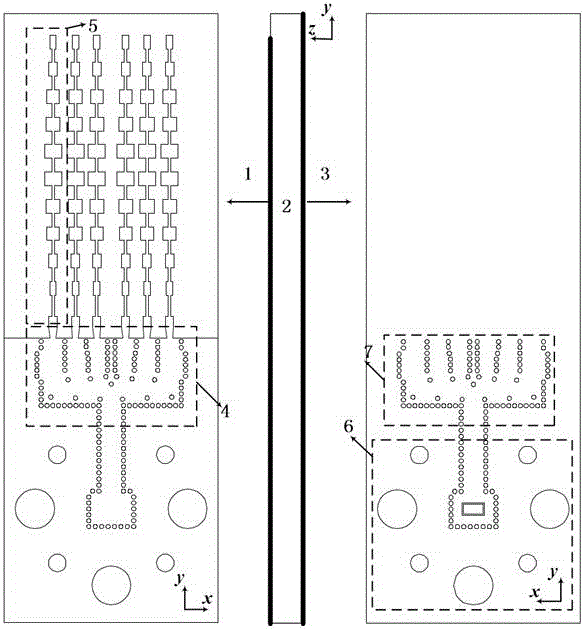
[0034] Such as figure 1 As shown, the antenna array structure involved in the present invention includes an upper metal structure 1 , a dielectric substrate 2 and a lower metal structure 3 . The antenna array structure includes a series-fed microstrip linear array radiating unit 5 , a feed network 4 (7 is the rear view of the feed network) and a SIW-to-standard rectangular waveguide 6 . The substrate integrated waveguide power divider of the feed network 4 has a one-way splitting 2N-way structure, where N is an integer greater than or equal to 3, and in this embodiment, N is 3. The antenna array of the feed network has 6 linear array radiation elements along the +x direction, and all the above parts together form an overall antenna array. All circular holes in the figure represent metallized vias. The linear array radiation unit 5 is in the form of a series-fed mic...


PUM


Abstract

The invention discloses an antenna structure and a design method thereof. The antenna structure comprises a linear array radiation unit and a substrate integrated waveguide feeding network, wherein an output end of the substrate integrated waveguide feeding network is connected with an input end of the radiation unit, a substrate integrated waveguide power distributor is of a structure for dividing one path into six paths, the structure for dividing one path into six paths comprises an input passage and six output passages, a metal hole is formed in an inlet of each output passage and is used for adjusting power and phase of the output passage, and an outlet of each output passage is connected with the radiation unit. By the antenna structure, an intermediate-long combined antenna based on a compact feeding network is achieved, and the size of the feeding network is greatly reduced. By the antenna, the demands of intermediate-distance test and long-distance test of a radar can be simultaneously satisfied, a millimeter-wave switch is not needed to switch among various antennas, and meanwhile, the antenna structure has the advantages of compactness, low cost, low profile, small size and the like.

Description

technical field [0001] The invention relates to the fields of electronics, microwave radio frequency, radar and the like, and in particular relates to a structure and a design method of a novel array antenna. [0002] technical background [0003] status quo [0004] As a key component of the radar system, the antenna has a very important influence on the index performance of the whole system. There are three main types of ranging radars: long-range, medium-range, and short-range. According to the radar equation: detection of farther targets requires greater equivalent isotropic radiated power (EIRP), and actual conditions do not allow an unlimited increase in transmit power. If you want to detect longer distances, you need an antenna array with higher gain. In most application scenarios, it is hoped that the radar will work in multiple modes, that is, to meet the detection requirements of medium and long distances at the same time. The existing schemes generally have the...

Claims


Application Information

Patent Timeline
IPC IPC(8): H01Q1/50H01Q3/30H01Q21/00
CPCH01Q1/50H01Q3/30H01Q21/00H01Q21/0006Y02D30/70
Inventor 洪伟余英瑞张慧
Owner SOUTHEAST UNIV
Why Eureka
Try Eureka