
Down-conversion method of reconfigurable microwave photonics and down-conversion device of the same

A technology of microwave photonics and frequency conversion devices, applied in the field of microwave photonics, can solve problems such as low conversion efficiency, limited frequency range of radio frequency signals, inability to flexibly control the frequency of down-converted intermediate frequency signals, etc., and achieve the effect of reducing requirements

Active Publication Date: 2017-05-17
UNIV OF ELECTRONICS SCI & TECH OF CHINA
View PDF7 Cites 18 Cited by
  • Summary
  • Abstract
  • Description
  • Claims
  • Application Information

AI Technical Summary

Problems solved by technology

Among them, the series or parallel electro-optical modulation method loads the radio frequency signal to be processed and the electrical local oscillator signal to two different electro-optic modulators respectively, uses an optical filter to select two modulated optical sidebands with adjacent frequencies, and then passes the photoelectric detection The beating frequency of the device is used to achieve down-conversion. This solution requires a high-frequency electrical local oscillator source, and due to the limitation of the filtering bandwidth of the optical filter, the frequency range of the RF signal to be processed is limited, and the conversion efficiency is low; The principle of electrical oscillation realizes the generation of high-quality local oscillator signals without additional high-frequency electrical local oscillator signals, but due to the existence of oscillation systems and broadband microwave devices, the complexity and cost of the system are increased; the optical frequency comb heterodyne method uses loading The modulated optical sideband of the RF signal to be processed and the optical frequency comb are used for heterodyne beat frequency, which can realize the down-conversion processing of RF signals in any frequency band without additional electrical local oscillator signals. However, since only the optical frequency comb is used as the optical local The frequency of the vibration source and down-converted intermediate frequency signal cannot be flexibly controlled, and it is difficult to deal with RF signals of different bandwidths

Method used


Image

  • Down-conversion method of reconfigurable microwave photonics and down-conversion device of the same
  • Down-conversion method of reconfigurable microwave photonics and down-conversion device of the same
  • Down-conversion method of reconfigurable microwave photonics and down-conversion device of the same

Examples


Embodiment 1

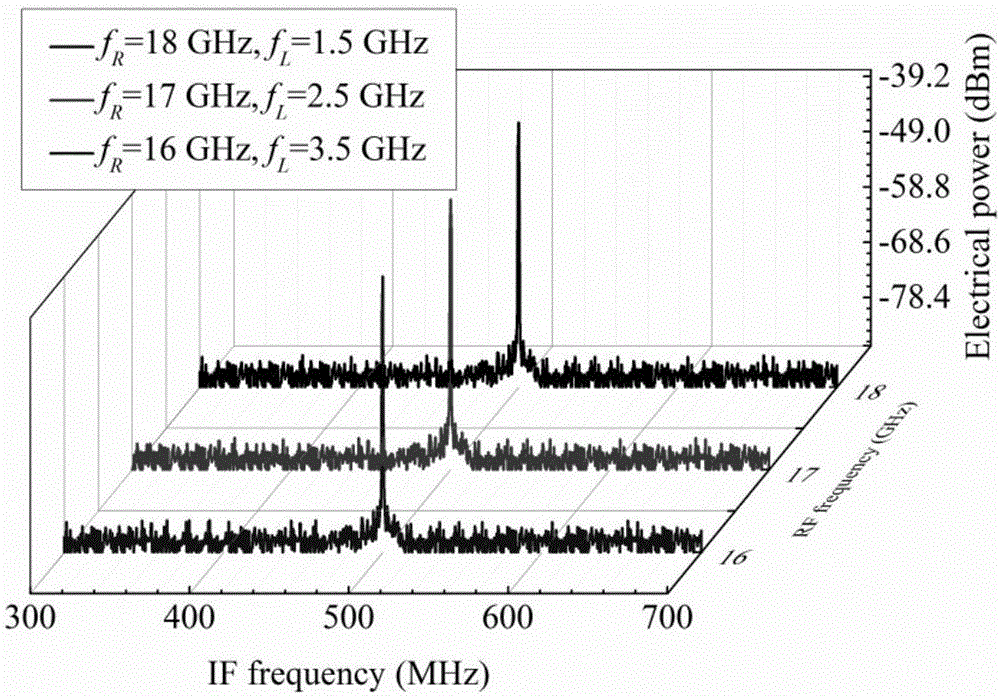
[0043] Down-convert radio frequency signals to be processed at different frequencies to intermediate frequency signals of the same frequency.

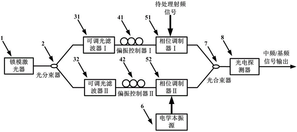
[0044] The frequencies of the RF signals to be processed are 16GHz, 17GHz and 18GHz respectively, and the filter windows of the adjustable optical filter I31 and the adjustable optical filter II32 are set, and the repetition frequency is f s The optical frequency comb signal output by the mode-locked laser 1 of =10GHz is filtered, and the frequency difference obtained is Nf s = 20GHz (N = 2) two beams of optical carriers with different frequencies, the corresponding frequencies are f 0 = 193.55THz and f 0 +Nf s = 193.57 THz. Set the frequency of the electrical local oscillator source to f L =3.5GHz, 2.5GHz and 1.5GHz, the frequency of the intermediate frequency signal corresponding to the down-conversion is |f R -Nf s |-f L = 500MHz. figure 2 Schematic diagram of down-converting RF signals to be processed with frequencies of 1...

Embodiment 2

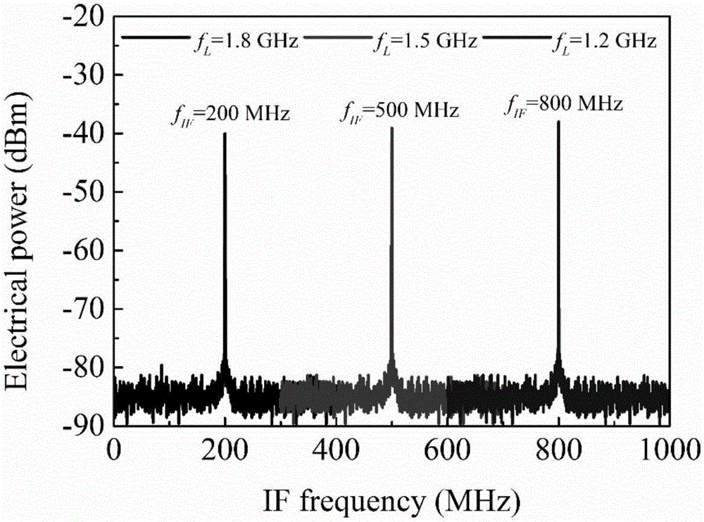
[0046] Down-convert the same radio frequency signal to be processed to an intermediate frequency signal of a different frequency.

[0047] The frequency of the RF signal to be processed is 18 GHz, and the filtering windows of the adjustable optical filter I31 and the adjustable optical filter II32 are set, and the repetition frequency is f s The optical frequency comb signal output by the mode-locked laser 1 of =10GHz is filtered, and the frequency difference obtained is Nf s = 20GHz (N = 2) two beams of optical carriers with different frequencies, the corresponding frequencies are f 0 = 193.55THz and f 0 +Nf s = 193.57 THz. Set the frequency of the electrical local oscillator source to f L = 1.8GHz, 1.5GHz and 1.2GHz, the frequency of the intermediate frequency signal corresponding to the down-conversion is |f R -Nf s |-f L = 200MHz, 500MHz and 800MHz. image 3 Schematic diagram of down-converting the RF signal to be processed with a frequency of 18 GHz to IF signals ...


PUM


Abstract

The invention relates to a down-conversion method of reconfigurable microwave photonics and down-conversion device of the same. The down-conversion method of the reconfigurable microwave photonics and the down-conversion device of the same are characterized by providing a method of being capable of satisfying the demand of the down-conversion of microwave photonics of arbitrary frequency bands and broadband radio-frequency signal, meanwhile capable of lowering the requirement of high frequency electrical local-oscillator signal source, avoiding using the high frequency electrical local oscillator. An optical frequency comb signal inputted into an optical frequency mixing structure is filtered. Two light carriers with different frequencies are produced by the filtering towards the optical frequency comb signal inputted into the optical frequency mixing structure, achieving optical local-oscillator of tunable frequency space. Pending radio-frequency signal is modulated on one light carrier through a phase modulator arranged at the optical frequency mixing structure. Pending radio-frequency signal is modulated on the other light carrier through another phase modulator arranged at the optical frequency mixing structure. Down-conversion signal is achieved through beat frequency for adjacent first-order light sidebands generated by the phase modulation, through the detection of a photodetector. The down-conversion method of the reconfigurable microwave photonics and the down-conversion device of the same have the advantages of achieving the down-conversion of microwave photonic of different frequency bands and broadband radio-frequency signal through changing the frequency space of the optical local-oscillator and setting the frequency of the electrical local-oscillator.

Description

technical field [0001] The invention belongs to the technical field of microwave photons, and in particular relates to a reconfigurable microwave photon down-conversion method and a microwave photon down-conversion device. Background technique [0002] The mixer is an indispensable frequency conversion basic device in the communication system. With the high carrier frequency and large broadband optical carrier microwave system becoming the development trend of optical fiber communication in the future, the traditional electrical frequency conversion technology is limited by the working bandwidth, low isolation, and loss. It is becoming more and more difficult to meet the current demand due to the influence of problems such as large size and low conversion efficiency. Microwave photonic frequency conversion technology makes full use of the advantages of photonic technology, such as large bandwidth, low transmission loss, and high isolation, to realize down-conversion of high-...

Claims


Application Information

Patent Timeline
Patent Type & Authority Applications(China)
IPC IPC(8): H04B10/548H04B10/60H04B10/70
CPCH04B10/548H04B10/60H04B10/70
Inventor 张尚剑邹新海王恒张雅丽刘永
Owner UNIV OF ELECTRONICS SCI & TECH OF CHINA
Learn More