Configuration method and device for radio bearer
A wireless bearer and configuration method technology, applied in wireless communication, electrical components, connection management, etc., can solve problems such as decreased business fluency, large system processing complexity, and reduced data service experience, and achieves a solution that reduces complexity and burden. Effect
- Summary
- Abstract
- Description
- Claims
- Application Information
AI Technical Summary
Problems solved by technology
Method used
Image
Examples
Embodiment 1
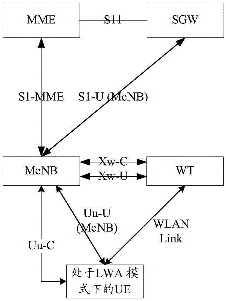
[0085] Image 6 This is an architecture diagram of the LTE DC mode and LTE LWA mode joint coexistence configuration network node structure provided by the first embodiment of the present invention. Such as Image 6 As shown, the WT is directly connected to the MeNB through the external Xw interface (or the WT is built into the MeNB). For example, the UE will be configured with the following three radio links at the same time: MCG Link (Uu-U (MeNB)), SCG Link (Uu- U(SeNB)), WLANLink. It is assumed here that there is still only one set of WLAN-related modules inside the UE, so only one WLAN Link can be supported; if there are multiple sets of WLAN-related modules inside the UE, the UE may support multiple WLAN Links, and the UE can be configured with more than three at the same time. Wireless link.
[0086] In this embodiment, it is assumed that the initial state of the UE is neither in DC mode nor in LWA mode. When the core network MME initiates the establishment of the first DRB...
Embodiment 2
[0106] Picture 8 It is a schematic diagram of deployment of Embodiment 2 of the present invention. reference Picture 8 The description of this embodiment is as follows:
[0107] Such as Picture 8 As shown, the primary (macro) base station MeNB and the secondary (micro) base station SeNB are connected through the X2 interface, and the MeNB / SeNB is connected to each independent WT / AP node through the Xw interface. Both MeNB / SeNB and WT / AP support related DC mode and LWA mode operation;
[0108] The UE is already in the RRC connected state at a certain moment, and is under good signal coverage of the potential target MCG serving cell (a group of cells under the MeNB), the SCG serving cell (a group of cells under the SeNB), and the MCG side WT / AP. The signal coverage of the WT / AP on the side is poor; the UE supports related DC mode and LWA mode operations;
[0109] The MeNB generates a restriction rule table for coexistence of DRB types, such as the example described in the first em...
Embodiment 3
[0116] Picture 9 It is a schematic diagram of deployment of Embodiment 3 of the present invention. reference Picture 9 The description of this embodiment is as follows:
[0117] Such as Picture 9 As shown, the primary (macro) base station MeNB and the secondary (micro) base station SeNB are connected through the X2 interface, and the MeNB / SeNB is connected to each independent WT / AP node through the Xw interface. Both MeNB / SeNB and WT / AP support related DC working mode and LWA working mode;
[0118] The UE is already in the RRC connected state at a certain moment and is under good signal coverage of the potential target MCG serving cell (a group of cells under the MeNB), the SCG serving cell (a group of cells under the SeNB), and the SCG side WT / AP. The signal coverage of the WT / AP on the side is poor; the UE supports related DC mode and LWA mode operations;
[0119] The MeNB generates in advance a restriction rule table for the DRB type coexistence configuration, for example,...
PUM
 Abstract
Description
Claims
Application Information
 - R&D
- Intellectual Property
- Life Sciences
- Materials
- Tech Scout
- Unparalleled Data Quality
- Higher Quality Content
- 60% Fewer Hallucinations
Browse by: Latest US Patents, China's latest patents, Technical Efficacy Thesaurus, Application Domain, Technology Topic, Popular Technical Reports.
© 2025 PatSnap. All rights reserved.Legal|Privacy policy|Modern Slavery Act Transparency Statement|Sitemap|About US| Contact US: help@patsnap.com


