Spiral negative pressure extraction booster

A booster and screw technology, which is applied in the field of medical devices, can solve the problems of time-consuming and laborious, difficult operation, difficult to advance at a uniform speed, etc., and achieve the effect of easy use and convenient disassembly

Active Publication Date: 2017-05-24
THE FIRST AFFILIATED HOSPITAL OF ZHENGZHOU UNIV
View PDF7 Cites 8 Cited by
  • Summary
  • Abstract
  • Description
  • Claims
  • Application Information

AI Technical Summary

Problems solved by technology

When using a syringe for nasal feeding, because the suction and the tube are divided into two steps, it is often necessary to repeatedly pull out the gastric tube and then connect it again. , Gastric tube is easy to enter air and liquid food backflow and other problems. At present, in medical supplies, doctors basically use syringes to feed liquid food or extract peritoneal effusion. The steps are cumbersome, the operation is complicated, time-consuming and labor-intensive
[0003] At present, there are booster-assisted liquid food feeding methods on the market. For example, the patent No. CN201520727469.5 discloses a booster device, which is mainly a hand-held artificial screw-type booster. The device slows down the manpower and time of the doctor in the process steps to a certain extent, and improves the efficiency to a certain extent, but as a manual propulsion, it is difficult to push at a constant speed, and the propulsion rod cannot be quickly disassembled from the device. The replacement cannot be done quickly, and the device cannot effectively clamp the syringe or the syringe output head and catheter effectively

Method used


Image

  • Spiral negative pressure extraction booster
  • Spiral negative pressure extraction booster
  • Spiral negative pressure extraction booster

Examples


Embodiment Construction

[0025] In order to make the object, technical solution and advantages of the present invention clearer, the present invention will be further described in detail below in conjunction with the accompanying drawings and embodiments. It should be understood that the specific embodiments described here are only used to explain the present invention, not to limit the present invention.

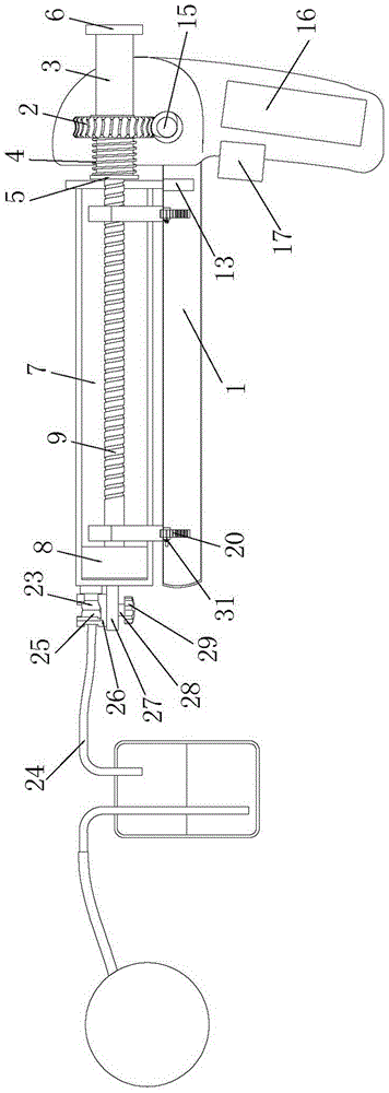
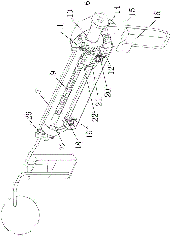
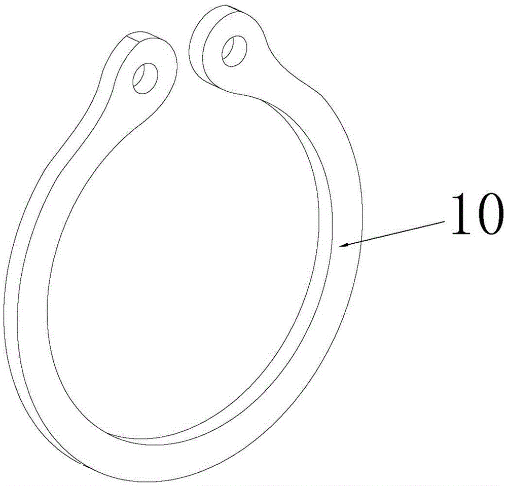
[0026] see Figure 1-5 , a spiral negative pressure extraction booster of the present invention, comprising: a housing 1, a driving member, a runner 2, a sliding sleeve 3, a spring 4, a first chuck 5, a second chuck 6, a syringe 7, a piston 8. Screw rod 9, retaining ring 10; the driving member and sliding sleeve 3 are arranged on the housing 1, the sliding sleeve 3 is provided with a keyway 11, and the runner 2 is installed in the keyway through a sliding key (not shown) 11 is sleeved on the sliding sleeve 3, the first chuck 5 and the second chuck 6 are connected to both ends of the sliding sleeve...


PUM


Abstract

The invention relates to a spiral negative pressure extraction booster which comprises a shell, a driving part, a rotary wheel, a sliding sleeve, a spring, a first clamping disc, a second clamping disc, an injector, a piston, a lead screw and a check ring. The driving part and the sliding sleeve are arranged on the shell, a key groove is formed in the sliding sleeve, and the rotary wheel is mounted in the key groove through a sliding key and arranged on the sliding sleeve in a sleeving mode. The first clamping disc and the second clamping disc are connected to the two ends of the sliding sleeve, the position, between the first clamping disc and one side of the rotary wheel, of the sliding sleeve is sleeved with the spring, the position, at the other side of the rotary wheel, of the sliding sleeve is sleeved with the check ring, and the piston and the lead screw are connected and then arranged in the injector. An output opening is formed in the injector, and the lead screw penetrates out of the injector and is mounted in the sliding sleeve in the mode of being engaged with an internal thread. The driving part is used for driving the rotary wheel, the sliding sleeve and the lead screw to rotate in sequence to drive the piston to move, and power driving is more constant in speed and more reliable. The second clamping disc is pulled to vacate space to facilitate separation and clamping of a fixed sheet and a clamping groove, the injector can be demounted and mounted conveniently, reset is carried out through the elastic force of the spring, and use is more convenient.

Description

technical field [0001] The invention relates to the technical field of medical devices, in particular to a spiral negative pressure extraction booster. Background technique [0002] In medical practice, some patients cannot finish eating due to nerve paralysis, hemiplegia, muscle weakness and coma. For a short period of time, it is enough to add some nutrient solution during the infusion, but some patients have a long course of disease and need to be fed with food while infusion of nutrient solution. If the patient is unable to eat, the only option is to inject liquid or semi-liquid food with a gastric tube. For severe patients who have lost the ability to swallow, a gastric tube is usually used to deliver liquid food, liquid medicine and beverages into the esophagus through the nasal cavity, which is called nasal feeding. The current nasal feeding method is to first use a syringe to inhale liquid food, liquid medicine, etc., and then connect it to a gastric tube and injec...

Claims


Application Information

Patent Timeline
Patent Type & Authority Applications(China)
IPC IPC(8): A61J15/00
CPCA61J15/0076
Inventor 韩新巍任克伟水少锋吴刚任建庄周朋利孙奇勋李臻王艳丽马波路慧彬毕永华吴正阳李亚华张文哲
Owner THE FIRST AFFILIATED HOSPITAL OF ZHENGZHOU UNIV
Why Eureka
Try Eureka