High-concentration high-stability negative-oxygen-ion therapeutic chamber

A negative oxygen ion, high stability technology, applied in treatment, treatment room, electrotherapy, etc., can solve the patient's discomfort and other problems, and achieve satisfactory treatment effect

Inactive Publication Date: 2017-05-24
崔贵福
View PDF0 Cites 0 Cited by
  • Summary
  • Abstract
  • Description
  • Claims
  • Application Information

AI Technical Summary

Problems solved by technology

[0004] At present, the negative oxygen ion treatment carried out in the hospital usually requires the patient to lie in front of the negative oxygen ion machine and take a deep breath in front of the machine. This treatment method makes the patient very uncomfortable.

Method used


Image

  • High-concentration high-stability negative-oxygen-ion therapeutic chamber

Examples


Embodiment Construction

[0014] The present invention will be further described below in conjunction with accompanying drawing:

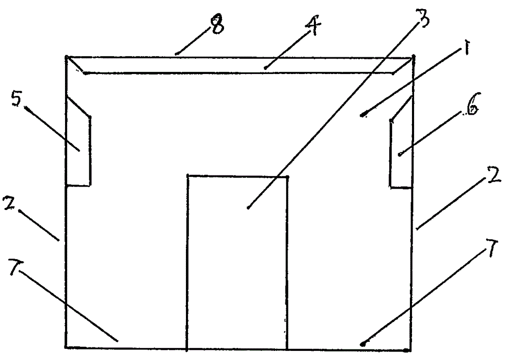
[0015] Accompanying drawing is the schematic diagram of this treatment cabin, among the figure treatment cabin four walls 2, namely the enclosure wall of treatment cabin adopts insulating material to make, and negative oxygen ion generating device 4 is installed on the position of cabin roof 8, and negative oxygen ion generating device 4 The carbon fiber on the ion releaser is installed facing the bilge, and the bilge 7 is made of conductive material, and a reliable grounding device is provided. As long as the installation positions of the humidity controller 5 and the temperature controller 6 do not affect the patient and the operator, no matter Wall-mounted or floor-mounted.


PUM


Abstract

The invention discloses a high-concentration high-stability negative-oxygen-ion therapeutic chamber. In the therapeutic chamber, a negative-oxygen-ion generator is mounted in the top of a chamber body, an ion releaser is prepared from a carbon fiber material whose area is the same with that of the chamber top, the plate is full of carbon fibers; and a chamber bottom made of a conductive material is grounded reliably; and four walls of the therapeutic chamber are made of an insulating material, and automatic humidity and temperature controllers are mounted in the chamber.

Description

[0001] Technical field: [0002] The invention relates to a negative oxygen ion treatment device, more specifically, it relates to a negative oxygen ion treatment cabin with high concentration and good stability. [0003] Background technique: [0004] At present, the negative oxygen ion treatment carried out in the hospital usually requires the patient to lie down in front of the negative oxygen ion machine and take a deep breath in front of the machine. This treatment method makes the patient very uncomfortable. [0005] Invention content: [0006] The purpose of the invention is to overcome the disadvantages of the prior art and provide a convenient and comfortable cabin type negative oxygen ion bath treatment device. [0007] The technical scheme of the present invention is: this high-concentration and high-stability negative oxygen ion treatment cabin is to install the negative oxygen ion generating device on the top of the cabin body, and the ion releaser of the negative...

Claims


Application Information

Patent Timeline
IPC IPC(8): A61N1/44A61G10/00
Inventor 崔贵福
Owner 崔贵福
Why Eureka
Try Eureka