A jet suction stirring flotation machine

A flotation machine and flotation technology, applied in flotation, solid separation and other directions, can solve the problems of reduced injection efficiency, reduced stirring efficiency, disturbed stirring flow field, etc., to reduce flotation energy loss, reduce frictional energy loss, The effect of avoiding dead zones

Active Publication Date: 2022-06-28
ANHUI UNIV OF SCI & TECH
View PDF7 Cites 0 Cited by
  • Summary
  • Abstract
  • Description
  • Claims
  • Application Information

AI Technical Summary

Problems solved by technology

[0002] Commonly used flotation machines are roughly divided into mechanical flotation machines and jet flotation machines. For the commonly used jet flotation machines, because there is no stirring device, when the pulp concentration is high, it cannot provide enough power to realize the pulp, Fully mixed and dispersed air bubbles and flotation reagents; while the high speed of the stirring device of the mechanical stirring flotation machine requires high energy consumption, and the low speed cannot form a good flow field and suction volume, and the new jet suction In the air agitation mechanism, since the jet stream submerged by the slurry in the injection section is close to the plume, most of the injection energy is consumed by the slurry, so the injection efficiency is greatly reduced, the agitation efficiency is greatly reduced, and the agitation flow field is disturbed

Method used


Image

  • A jet suction stirring flotation machine
  • A jet suction stirring flotation machine

Examples


Embodiment Construction

[0018] As shown in the figure, in order to realize above-mentioned purpose, the present invention adopts following technical scheme:

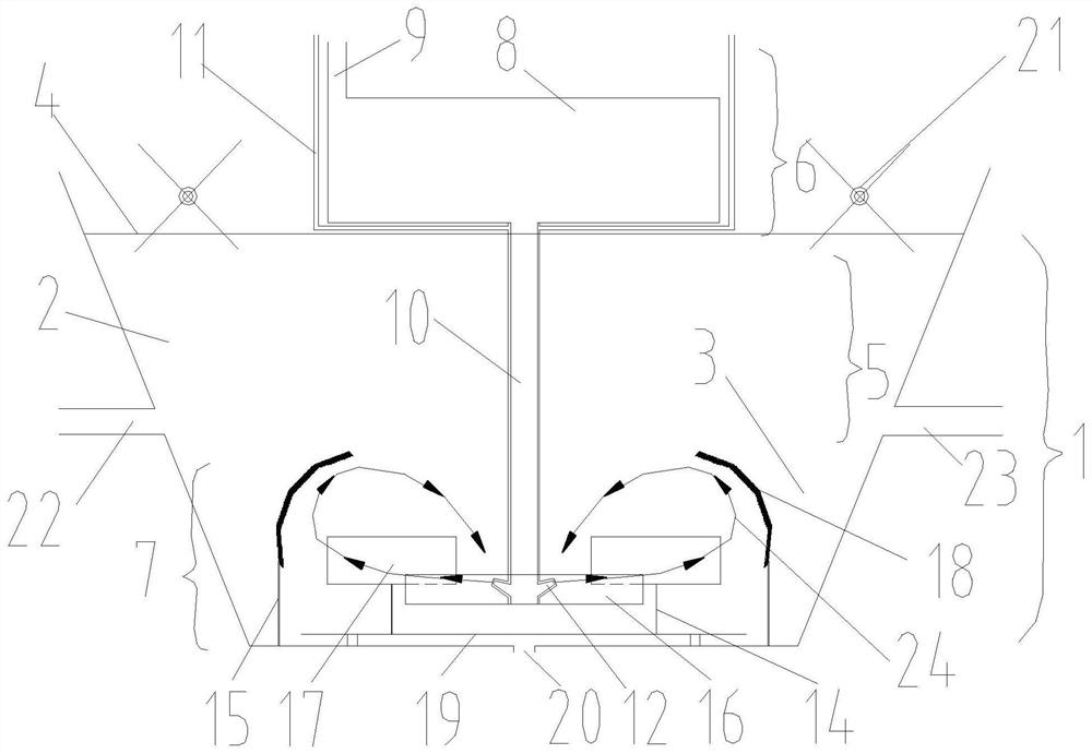
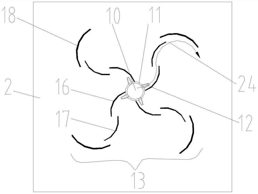
[0019] A jet suction stirring flotation machine comprises a suction mixing mechanism (1), a flotation cell (2), a first support (4), and an ore pulp transport area (5);

[0020] The suction mixing mechanism (1) includes a feeding zone (6) and a stirring and mixing zone (7).

[0021] The feeding area (6) is located on the upper side of the first support (4), and is composed of a mixing bin (8), a circulating feeding port (9), and a suction pipe (10); the mixing bin (8) It is arranged on the upper end of the first support (4) and is used to hold the flotation circulating pulp. The circulating feed inlet (9) is arranged above the mixing bin (8), and the feeding pipe (10) is arranged at the mixing bin (8). The lower end of the silo (8) is communicated with the mixing silo (8);

[0022] The stirring and mixing zone (7) comprises a feeding pipe (10...


PUM


Abstract

The invention belongs to the technical field of mineral separation, and specifically relates to a jet-suction agitation flotation machine. The flotation machine adopts deflectors to replace the stirring impeller of the mechanical agitation flotation machine, which reduces the frictional energy between the impeller and the shaft. Loss and internal energy loss caused by impeller agitation of slurry reduces flotation energy loss. The static deflector guides the submerged jet inflow three times, accompanied by the sweeping and stirring of the pulp in the tank, so that the pulp, chemicals and air bubbles are fully mixed in a wider range in the tank. At the same time, the static deflector can realize the control of the pulp mixing circulation area by inducing the direction of the pulp flow, so as to prevent the pulp mixing circulation area from interfering with the transport area of ​​mineralized air bubbles and the foam layer, forming a good flotation environment and the deflector Through multiple cutting and impact crushing of large air bubbles in the pulp, air bubbles with smaller particle sizes are formed, and are fully and evenly distributed in various sections of the tank along the deflector to achieve full mineralization.

Description

technical field [0001] The invention belongs to the technical field of mineral separation, and in particular relates to a jet suction stirring flotation machine. Background technique [0002] Commonly used flotation machines are roughly divided into mechanical flotation machines and jet flotation machines. For the commonly used jet flotation machines, because there is no stirring device, when the pulp concentration is high, it cannot provide enough power to realize the pulp, The bubbles and flotation agents are fully mixed and dispersed; while the high speed of the stirring device of the mechanical stirring flotation machine requires high energy consumption, and the low speed cannot form a good flow field and suction volume, and the new type of jet suction In the gas stirring mechanism, because the slurry in the jet section is submerged by the jet flow close to the plume, most of the jet energy is consumed by the slurry, so the jetting efficiency is greatly reduced, the stir...

Claims


Application Information

Patent Timeline
Patent Type & Authority Patents(China)
IPC IPC(8): B03D1/24
CPCB03D1/24B03D1/242
Inventor 朱金波朱文祥王超侯彬陈乾蔡俊杰王媛媛李燕琳
Owner ANHUI UNIV OF SCI & TECH
Why Eureka
Try Eureka